Steelwork fundamentals and an introduction to bolted connections
This is the recommended first lecture. Read the foundations on force, moment, stress and limit states, then follow the lecturer from steel properties into connection design. You do not need to memorise every table value yet. Learn which failure each check prevents and how to place the given data in the correct expression.
Abbreviations: DL—Dead Load; LL—Live Load; ULS—Ultimate Limit State; SLS—Serviceability Limit State; UDL—Uniformly Distributed Load; LTB—Lateral-torsional Buckling; UB—Universal Beam; UC—Universal Column.
Key Points
- Strength, stability and serviceability (deflection and vibration) are three separate checks; state a conclusion for each.
- ULS uses factored loading, in this course. SLS deflection uses unfactored imposed load; convert limits such as to mm.
- For classification, determine from thickness, calculate , then compare and .
- Ordinary bolted connections require bolt shear, bolt bearing , plate bearing (minimum of four bounds) , plate tension and hole-spacing checks.
- Net area deducts hole width times plate thickness. Angles connected through one leg also require the course reduction.
Key Formulas
Exam Question Types
- Bolted angle connection: given loads and layout, check shear, bearing and angle tension. → Two M20 bolts connecting an angle: link the checks (Bolted Angle)
- Double-cover splice: determine bolt count and check spacing and main-plate tension. → 750 kN double-cover splice: separate capacity and spacing (Double-cover Splice)
Design flows for these question types
- Opening course arrangements and the 01:30–01:45 break have been omitted.
How steelwork can fail (Failure Modes)
What this unit is for: Steel is strong, yet a steel member can still break, buckle or deform too much; this unit separates these different problems one by one.
Picture it this way: A long steel wire is hard to snap by pulling, yet it bows out at once when pushed from both ends. A long plank used as a bridge does not break, yet it bounces a lot underfoot. Material failure, buckling and too much movement are three different problems.
Prerequisites: Material strength and member capacity (Stress and Resistance) · Instability can precede material crushing (Buckling) · Excessive bending deformation versus insufficient resistance (Deflection)
The lecturer introduces steel's advantages, then immediately discusses buckling and vibration. The sequence matters: stronger material does not remove problems caused by slender geometry, insufficient stiffness or inadequate restraint. Distinguish material failure, member instability and excessive service deformation first, so later formulas form a coherent system.
For a steel beam under downward loading, imagine the top and bottom flanges shortening and stretching respectively. For a column, imagine axial force travelling down its length. Then ask which plate is compressed, which direction may lack restraint, and whether the deformation is acceptable in use. These questions determine the checks; do not simply select the easiest formula to substitute into.
Several limits can apply to one member simultaneously. State specific conclusions such as “shear passes” and “deflection passes”, then combine all required checks. The course develops connection, beam and column checks in this way.
Steel carries tension, but compression buckling must also be prevented
Steel can carry tension and compression, but a slender compression member may become unstable before its material fully yields. High material strength does not guarantee freedom from buckling.
Vibration or deformation may also govern lightweight structures. Material should follow the internal-force demand; the lecturer uses bending moment diagrams to explain efficient steel use.
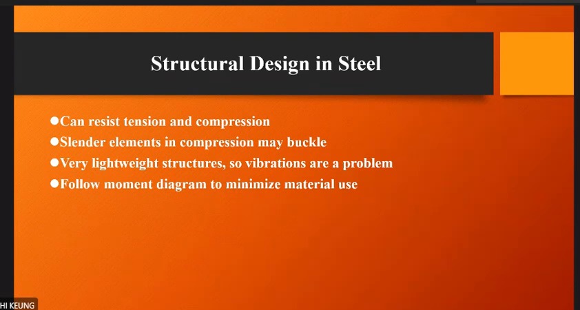
How to read this image: Read the advantages and applications first, then the limitations in the text. Material resistance, member stability and service deformation will be checked separately.
Strength failure and serviceability require separate checks
Strength issues include material failure and instability; serviceability concerns excessive deformation, vibration and damage to attached components.
Do not write only “safe”. State whether bending, shear, buckling or deflection satisfies its requirement.
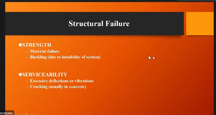
How to read this image: Match each illustrated instability or deformation to the member direction. Identify whether the discussion concerns strength, buckling or vibration.
Durability and fire protection are separate design considerations (Durability and Fire Protection)
What this unit is for: Steel rusts, and it loses strength when it gets hot; this unit explains that corrosion protection and fire protection are two matters separate from the strength calculation.
Picture it this way: A steel railing rusts first in the corner where water collects, and a blacksmith can bend steel easily once it glows red. Fire casing around steel works like an oven glove: it only keeps heat out and carries no load, so it is never counted as part of the steel section.
Prerequisites: Material strength and member capacity (Stress and Resistance)
The lecturer includes corrosion and fire protection in the material introduction to emphasise that a structure must perform beyond its completion date. Trapped moisture, surface protection and maintenance access affect long-term condition. These involve detailing and exposure conditions.
In an encasement drawing, identify the steel section first and then its external protective layer. Protection and structural force resistance have different roles. Do not add the encasement dimensions directly to the steel area or second moment of area .
This segment does not develop a fire-condition design example. The explanation therefore follows the lecturer's purpose without introducing another fire-design calculation method.
Durability: detailing to avoid trapped water and corrosion
Corrosion protection is more than applying paint. The lecturer first discusses detailing to prevent retained moisture, then stainless steel, galvanising and other protective coatings.
Protection depends on exposure, maintenance and connection details. Material-strength calculations alone do not constitute a complete design.
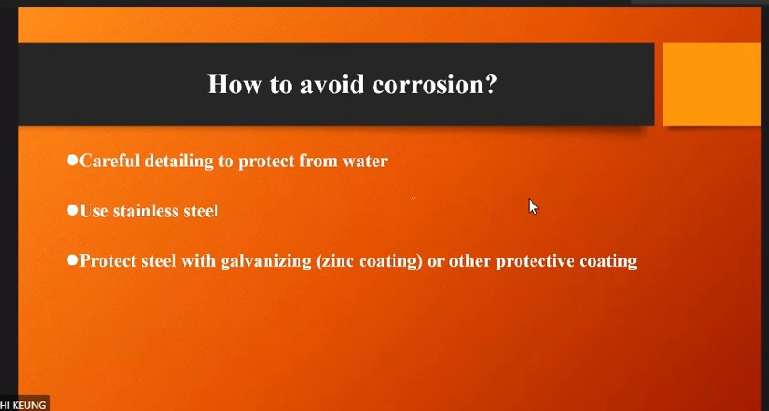
How to read this image: Identify details that trap water or hinder maintenance, then the protective measures. These are distinct from section-capacity calculations.
Fire resistance and member protection
Steel loses strength as temperature rises. Passing an ambient-temperature strength calculation does not replace a fire-resistance check.
The screen illustrates protection around I-sections and hollow sections. The point here is that fire resistance is a separate design consideration; no fire-design calculation is developed in this segment.
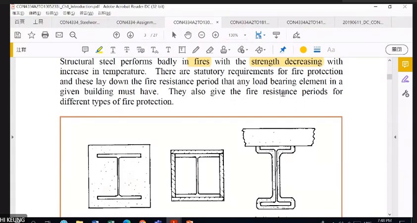
How to read this image: Identify the inner steel section and outer fire protection. Their roles differ; encasement dimensions are not steel area.
Separate ultimate and serviceability checks (Ultimate and Serviceability Limit States)
What this unit is for: A beam must be strong enough not to collapse, and it must not sag too much in daily use; this unit separates the two checks and the loads each one uses.
Picture it this way: A bookshelf board full of books does not break, yet it clearly sags in the middle: strong enough, but not stiff enough. Breaking is checked with increased loads, sagging with everyday loads, and the allowed sag changes with the span.
Prerequisites: When to check strength and when to check deformation (Limit States) · Excessive bending deformation versus insufficient resistance (Deflection) · Why the position of a force matters (Moment and Eccentricity)
At 00:57:20, the lecturer's notes explicitly identify the Hong Kong Code of Practice for the Structural Use of Steel 2011 as the course basis. The load combinations, table values and symbols below follow that code.
The lecturer establishes two questions: whether the structure can carry extreme design actions, and whether it deforms excessively during normal use. Start each problem with separate ULS and SLS load columns to avoid carrying the same factored value into every check.
The limits , and vary with span. Identify the member use and corresponding load condition, calculate the limit in mm, then compare deflection . For example, over a 9 m span is 25 mm, not 360 mm.
The lecturer also uses a displaced-column sketch to explain the additional moment when a force's line of action shifts. First understand times lateral displacement. Later column moment-amplification factors build on this idea; you need not derive a complete second-order analysis here.
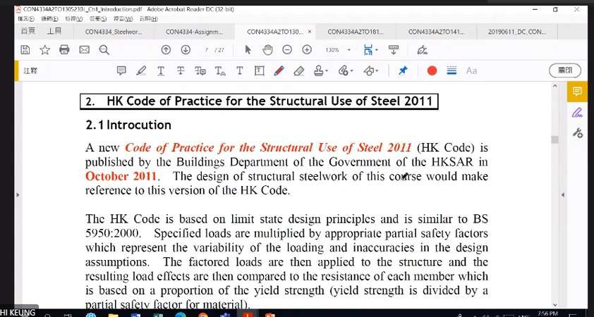
How to read this image: Read the 2011 edition at the top, then the statement adopting it for the course. It is the classroom basis for the design tables and combinations.
The meaning of ULS and SLS
The ultimate limit state (ULS) concerns collapse or irreparable damage. The serviceability limit state (SLS) concerns a structure becoming unsuitable for normal use.
The lecturer notes that SLS generally uses unfactored loads. Strength, stiffness and stability each require checks; passing one does not imply that all pass.
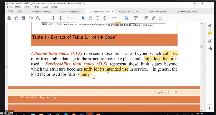
How to read this image: Read the ultimate and serviceability columns separately to establish two load conditions. Later examples maintain this distinction.
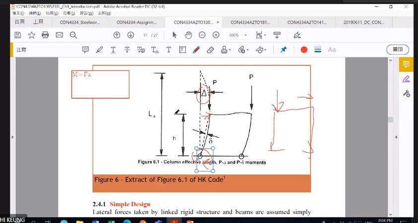
How to read this image: Locate downward and the column-axis displacement from its original position. Their product produces an additional moment.
Deflection limits must match the member and its finishes
The screen lists for cantilevers, for beams supporting plaster or other brittle finishes, and for the other beams in the table. The table specifies vertical deflection due to imposed load.
Read the intended use and load definition before selecting a limit. is not a fixed answer for every beam.
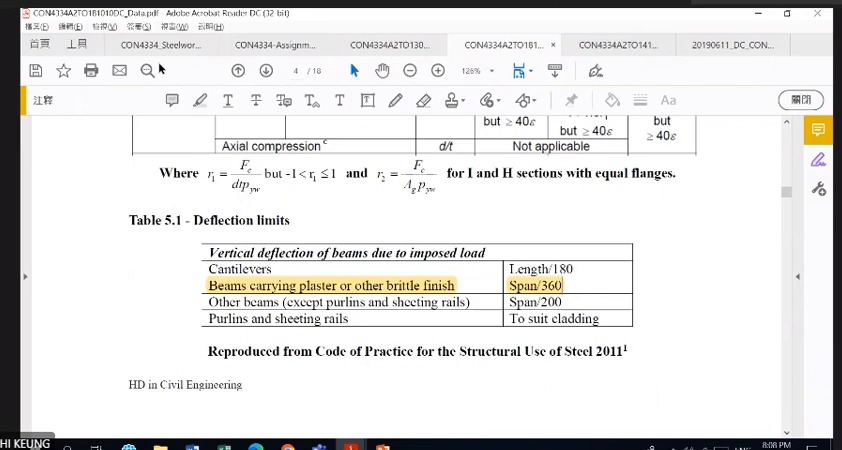
How to read this image: Identify the use and loading condition before reading , or . Convert the span consistently to obtain allowable deflection.
Read the section table before classifying (Section Tables and Classification)
What this unit is for: A wide, thin steel plate wrinkles first when it is squeezed; this unit reads the flange and web sizes from the section table and judges whether they are too thin.
Picture it this way: Stand on a drinks can and its thin wall wrinkles first, long before the aluminium itself is crushed. A flange or web that is too thin wrinkles early in the same way, so its width divided by its thickness is compared with a limit.
Prerequisites: Read an I-section and its section table (Section Properties) · Will the plate buckle before its material strength is fully mobilised? (Section Classification)
Classification needs actual plate geometry, not the nominal designation. Locate flange thickness , web thickness and effective depth on the section sketch before reading the table row. Do not confuse with , with , or with .
The lecturer uses to express limits for different design strengths in one table. Determine from thickness, calculate , then compare width-to-thickness ratios. Automatically taking for all S355 sections can select the wrong classification limit even if the arithmetic is correct.
The screenshot below shows the lecturer entering , , and for a 914×305×201 section into the classification table. Classification determines the bending resistance expression available.
Section classification: adjusting width-to-thickness limits with
Thin plates can buckle locally, so flange and web width-to-thickness ratios must be checked separately.
The course table is based on and uses to adjust for other design strengths. Look up by steel grade and thickness; S355 does not mean that 355 is always the applicable value.
- Identify flange thickness , web thickness , width and effective web depth in the section table.
- Select the correct loading type and plate boundary conditions, then compare the and limits.
- Use the less favourable plate classification for the whole section.
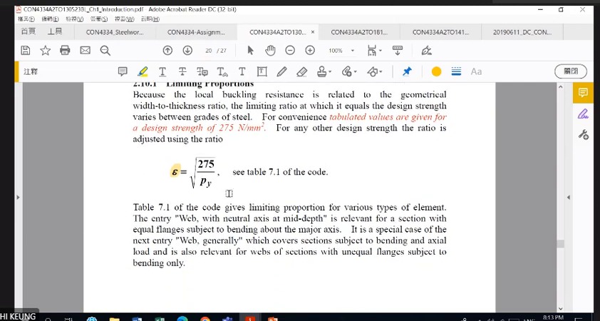
How to read this image: Select the plate type, then compare width-to-thickness ratios with the limits. Check both flange and web.
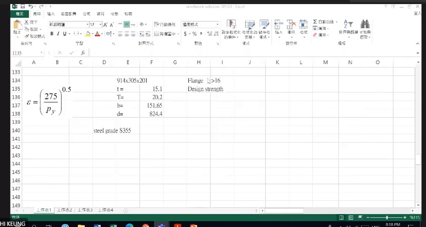
How to read this image: Identify thicknesses and , width and depth in turn. These values enter the classification table.
Force transfer and bearing in ordinary bolts (Bearing-type Bolts)
What this unit is for: An ordinary bolt passes force by the hole wall pressing on the bolt shank; this unit shows how hole position and plate thickness limit the force one bolt can pass.
Picture it this way: A belt pin sits in a belt hole. Pull too hard and the hole stretches out of shape; put the hole too near the end and the short piece of leather beyond it is torn away. A hole in a steel plate can fail in the same ways, and the weakest one decides.
Prerequisites: Several failure paths in a bolted connection (Bolted Connections) · How holes weaken a steel plate (Net and Effective Area) · Use units to identify what you are calculating (Units and Dimensions)
The lecturer moves from connection types to hole positions and then bearing expressions. Understand the force path before deciding which dimension belongs in each expression. Mark force-transfer arrows on the question drawing and identify end distance and clear hole spacing along that direction.
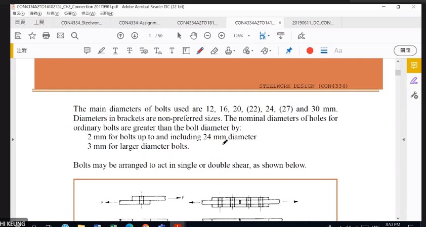
Bolt diameter and hole diameter differ because installation clearance is needed. Bolt shear, hole-wall bearing and plate net section each use defined dimensions. Grade 8.8 also describes the bolt, whereas S355 describes the angle or plate.
The four candidate plate-bearing values are not alternative methods to choose freely. They represent different limits, and the smallest applicable value governs. Keep each value's origin visible to understand which limit is improved by a larger end distance or thicker plate.
Bolts and welds transfer forces differently
The lecture first distinguishes ordinary bearing bolts, friction-grip bolts and welds. Ordinary bolt examples require checks of both the bolts and the connected plates.
Bolt grade, such as Grade 8.8, and plate grade, such as S355, describe different materials. Their strengths are not interchangeable.
How to read this image: Trace force transfer from plate to bolt in the joint drawing. Establish single or double shear before selecting the resistance expression.
How to read this image: Read the difference between hole and bolt diameters, then count plate interfaces in the side view.
Pitch, end distance and edge distance are essential dimensions
Measure end distance along the force-transfer direction. Interpret edge distance from the actual hole and plate-edge positions. Minimum distances depend on bolt size and conditions such as cut or rolled edges.
The lecture covers maximum spacing as well as minimum distances. Even when resistance passes, check that the actual hole arrangement satisfies detailing requirements.
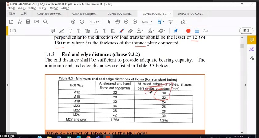
How to read this image: Distinguish pitch, end distance and hole diameter, measuring along the force arrow. They enter different detailing or bearing expressions.
Plate bearing is governed by the smallest applicable bound
Standard holes use ; the displayed oversized and short-slotted holes use smaller factors. Plate bearing also depends on end distance , clear hole spacing and material strength.
The screen gives for S355 plate bearing . This is not the Grade 8.8 bolt shear strength .
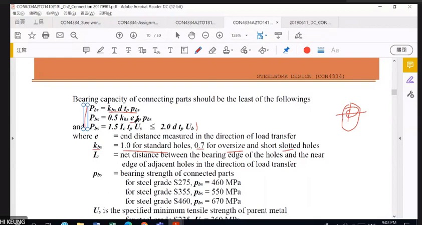
How to read this image: Read all four plate-bearing bounds and their material symbols. The last expression uses . Calculate each candidate and take the minimum.
First angle-connection example: complete shear first (Angle Connection Example)
What this unit is for: An angle in tension is held by two bolts; this unit first finds the design force, then checks whether the bolts would be sheared through.
Picture it this way: A heavy bag hangs on two hooks. First settle the weight of the whole bag, then halve it to get the load on each hook, and compare that with what one hook can take. Never compare the whole bag with one hook.
Prerequisites: Why an object can remain stationary (Forces and Equilibrium) · Several failure paths in a bolted connection (Bolted Connections) · When to check strength and when to check deformation (Limit States)
Two unfactored loads are given, so calculate the design force of 169 kN first. Then determine how many bolts and shear planes carry it. Write total force and force per bolt separately to avoid comparing one bolt's resistance with total demand.
The lecturer checks shear here and returns to the angle's effective area later. The complete worked example below connects all checks, including the bearing arithmetic not written out line by line in class, so that the governing mode becomes clear.
Complete worked examples in this unit: Two M20 bolts connecting an angle: link the checks (Bolted Angle)
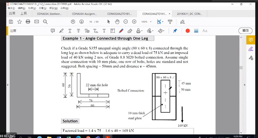
How to read this image: Copy the given-data table first. Distinguish the 22 mm hole from the 20 mm bolt, and the 10 mm connecting plate from the 8 mm angle.
Two M20 bolts: calculate the design force first
The original dead and imposed loads are 75 kN and 40 kN, giving 169 kN after factoring. Each M20 bolt uses a shear area of 245 mm² and Grade 8.8 strength .
Shear resistance is 91.875 kN per bolt, approximately 91.9 kN. Two bolts provide 183.75 kN, exceeding 169 kN. This completes only shear; bolt bearing , plate bearing and angle tension still require checking.
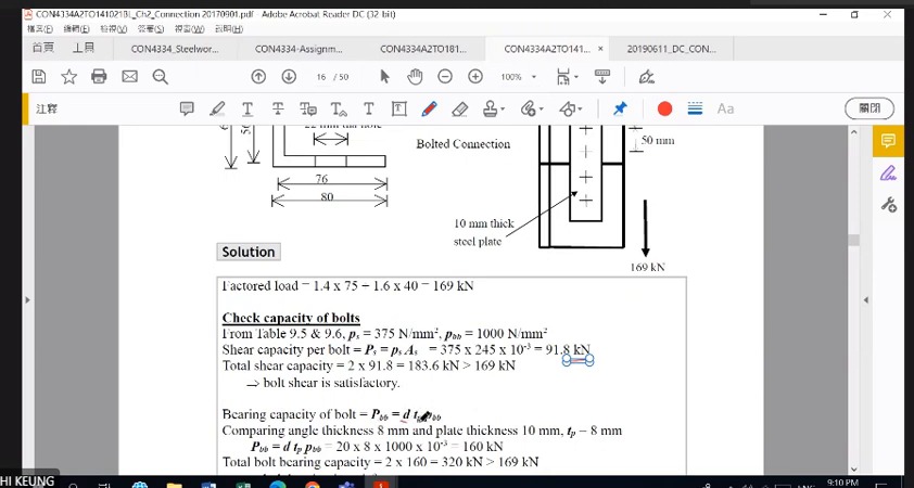
How to read this image: Read the 169 kN demand, then 91.875 kN per bolt or 183.75 kN for two. Compare demand and resistance at the same level.
Two M20 bolts connecting an angle: link the checks (Bolted Angle)
80×60×8 angle is fixed to a 10 mm plate by 2 M20 bolts in single shear. It is pulled by a dead load of 75 kN and an imposed load of 40 kN. Decide whether the bolts shear off, the hole walls crush, or the angle is pulled apart.
Solution Route: Calculate design force; check bolt shear, bolt bearing , thinner-plate bearing and angle effective-area tension in sequence. Finally check hole detailing separately.
The lecturer next checks the 750 kN splice and revises its spacing (Splice Layout Check)
What this unit is for: Two main plates are joined by two cover plates and bolts; this unit first checks that the bolts are enough, then checks that the hole spacing meets the rules.
Picture it this way: In a relay race the baton passes whole from the first runner to the second, then whole to the third. The pull moves the same way: the bolts on one side hand all of it to the cover plates, and the bolts on the other side hand all of it back. The two sides never share one load.
Prerequisites: Several failure paths in a bolted connection (Bolted Connections) · How holes weaken a steel plate (Net and Effective Area)
Two cover plates sandwich the main plate. Force passes through one half-joint into the covers, then through the other half back into the main plate. Draw this load path first to avoid dividing the force across bolts from both halves together.
The lecturer checks shear and bearing, uses the governing capacity to estimate bolt count, then finds insufficient transverse spacing during the geometry check and requires an adjustment. Resistance and detailing are consecutive design stages; “adequate” in a worksheet may still leave other conditions unresolved.
The lecturer briefly enters a bolt diameter of 20 mm, then corrects it to M24 for this question. Check the question, load and dimensions before copying values. The main plate's net-section tension is also checked: , exceeding 750 kN.
Complete worked examples in this unit: 750 kN double-cover splice: separate capacity and spacing (Double-cover Splice)
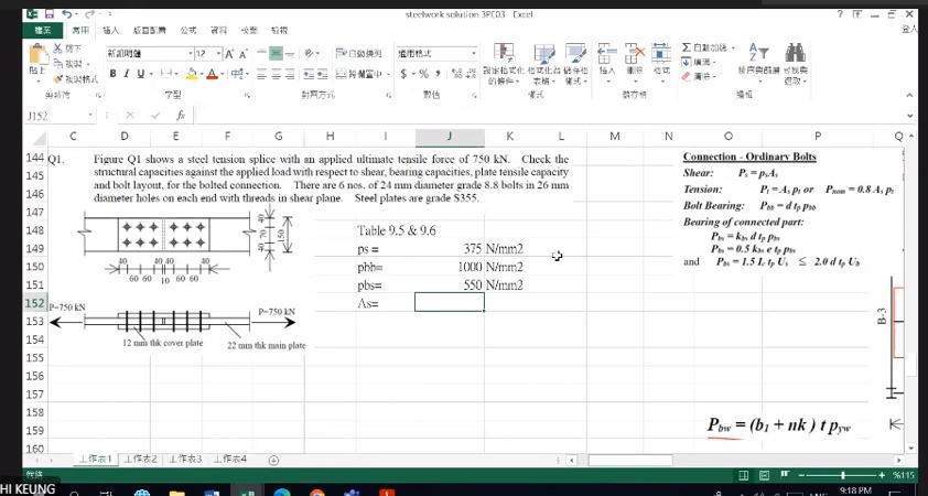
How to read this image: Read the 22 mm main plate and two 12 mm cover plates in side view, then the bolt arrangement in each half-joint.
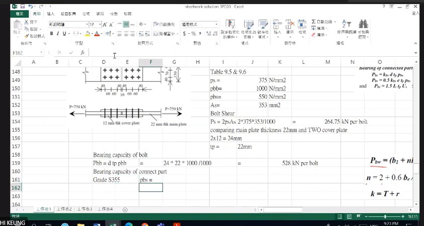
How to read this image: The double-shear factor 2 and combined cover thickness 24 mm belong to different steps. The governing contact thickness is 22 mm.
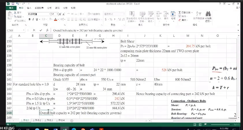
How to read this image: The first expression uses and gives 290.4 kN. The end-distance value of 242 kN is the minimum, so end distance governs.
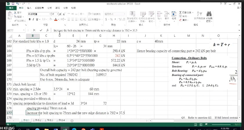
How to read this image: Read the required bolt count, then , and finally the instruction “Increase to 75 mm”.
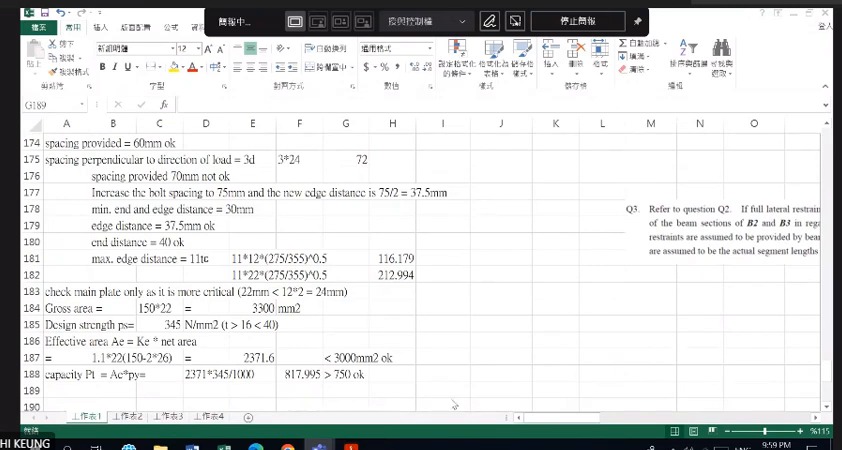
How to read this image: The 22 mm main plate is thinner than the combined 24 mm covers, so only the main plate is checked here. At 22 mm thickness, ; .
750 kN double-cover splice: separate capacity and spacing (Double-cover Splice)
Two main plates, 150 mm wide and 22 mm thick, are joined end to end by two 12 mm cover plates with 6 M24 bolts at each end. The ultimate pull is 750 kN. Decide whether the bolts, plate bearing and main plate are adequate, and whether the hole spacing meets the rules.
Solution Route: Identify double shear; find governing bolt/plate bearing ; estimate bolt count from resistance; finally check the arrangement.
Return to the angle: gross, net and effective areas (Gross, Net and Effective Area)
What this unit is for: Holes leave less steel to carry tension; this unit works out how much area is left to resist the pull after the holes are taken away.
Picture it this way: The row of small holes between stamps is where the paper tears most easily, because the least paper is left along that line. A steel plate in tension is also weakest along the line through its holes. An angle bolted through one leg gets less than full help from the other leg, so its area is reduced again.
Prerequisites: How holes weaken a steel plate (Net and Effective Area) · Material strength and member capacity (Stress and Resistance)
Holes weaken the section perpendicular to tension. Deduct their width within that section times plate thickness. The lecturer first obtains net area geometrically, then applies the course material factor for effective area , and finally reduces resistance for single-leg force transfer. Do not collapse these three stages into an unexplained number.
An angle has two legs, but the load enters only through the bolted leg. The other leg does not immediately participate in exactly the same way. The course uses a specified expression for this uneven force transfer. The later welded-angle coefficient differs; remember the connection type together with its expression.
Return to the complete angle example and compare its 248.2 kN tension resistance with shear and bearing in one table. This establishes which mode governs.
Net section and effective area
Holes weaken the tension path. Deduct holes from the relevant section, apply the course factor to obtain effective area , and retain the gross-area upper limit.
The screen lists for S275, 1.1 for S355 and 1.0 for S460. These are factors in this course's design method; do not combine them directly with symbols from other codes.
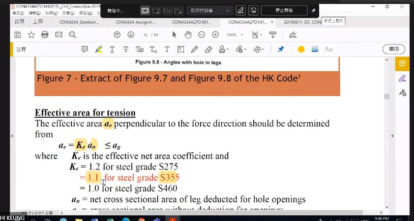
How to read this image: Identify and on the two legs, then deduct the intersected hole width. The resulting area is in mm², not the circular hole plan area.
Angles connected through one leg: reduce the contribution of the outstanding leg
The M20 bolts use the 22 mm holes shown. Connected-leg net area is (76−22)×8=432 mm²; outstanding-leg area is 56×8=448 mm².
The notes on screen multiply both legs together by 1.1 and get . The current lecture notes (Chapter 2, page 17) work leg by leg: connected leg 1.1×432=475.2 mm²; unconnected leg 1.1×448=492.8 mm², which exceeds its gross area, so 448 mm² is taken; , below . A bolted single-leg connection then needs a reduction for the unconnected leg; cannot be used directly.
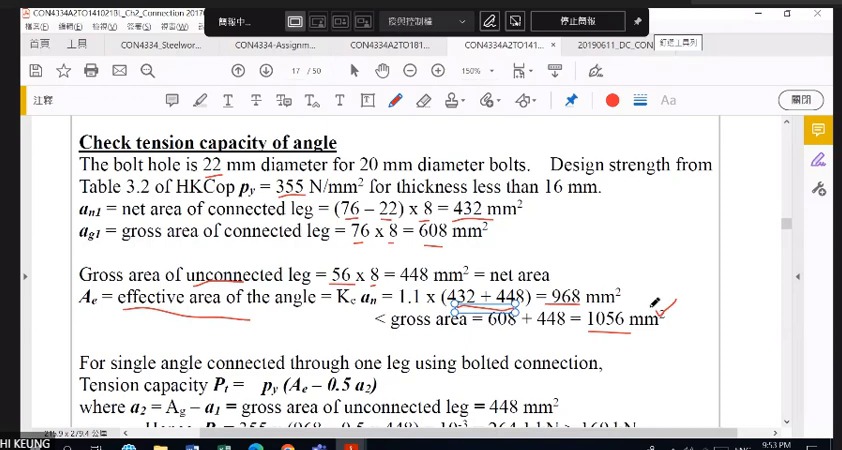
How to read this image: The notes on screen multiply both legs together by 1.1, giving and . The current lecture notes work leg by leg and cap the unconnected leg at its gross area of 448 mm², giving and .