Tutorial 2 Q7: separate flange and web weld design
Open “Animation lab” beside a teaching step for a visual explanation or a walkthrough of its original expressions. Models are illustrative; source answers remain unchanged.
Need a simpler picture? Open “Simple explanation” beside a difficult step. These optional notes do not replace the full solution.
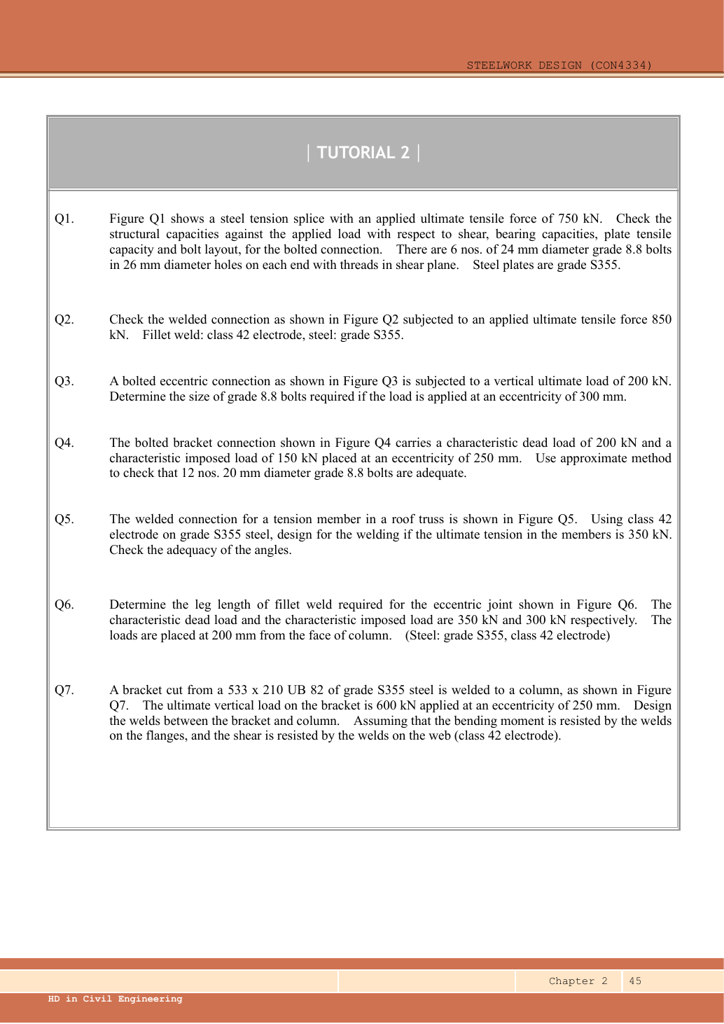
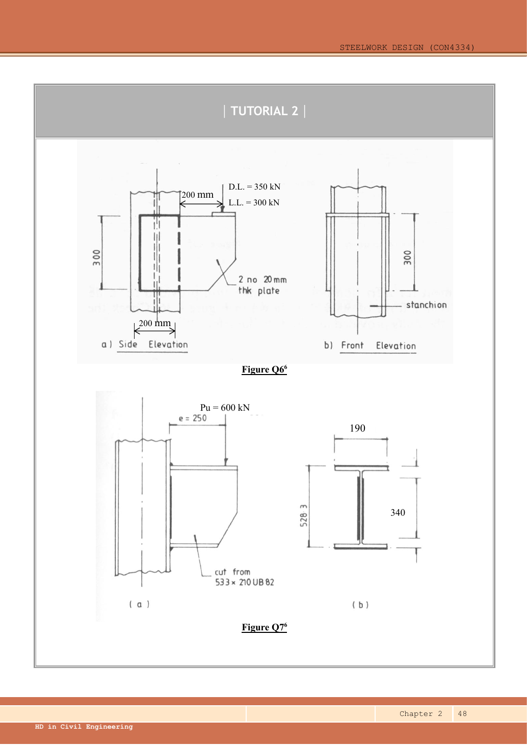
Design welds connecting a bracket cut from UB S355 to a column. Ultimate vertical load is at eccentricity . Use Class 42 electrode and the question’s assumption that flange welds resist moment while web welds resist shear.
Original source: LectureNotes/Ch 2_Connection.pdf — p. 45, p. 48. Values tagged given are in the question or diagram; lookup values come from a named table; calculated values follow from the working; assumptions are stated explicitly.
Read the diagram and collect the data
| Input | Meaning |
|---|---|
| Moment force couple | Use the source example’s overall-depth lever-arm approximation between flange force lines. |
| Flange run | One physical weld line at each flange, carrying the flange couple force. |
| Web runs | Two physical runs share direct shear. |
| Section thickness | Data File p.9 row : flange ,web . |
| Unspecified input | Column flange thickness is absent, affecting the minimum permitted weld size at the web/column joint. The strength design can be calculated; unconditional detailing depends on that thickness. |
Before calculating: recognition and strategy
Use the stated simplified load split rather than a full elastic weld-group analysis. Moment becomes an equal-and-opposite pair of flange forces ; the web takes the vertical shear. Size each family of welds using its own effective length. Because , changing the leg also changes the effective length; recheck the chosen trial.
1. Moment and flange welds
Simple explanation: How two flange forces make a moment
Two opposite forces form a turning pair, like two hands turning a wheel.
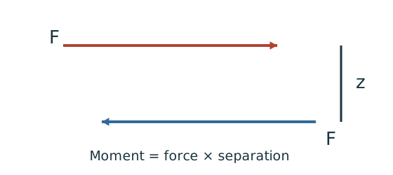
- Identify the separation between their actual force lines.
- Required force equals moment divided by that separation.
- Design the relevant flange group for that force.
Remember: The force-line separation is not automatically the overall section depth.
Provide fillet along each flange run. For flange edge, maximum leg permits 10. The thicker-part minimum is at most in the supplied table, so 10 meets it even if the column flange is thicker. Effective . The force in each flange is ; do not divide it by two merely because the couple has two flanges.
This force-couple idealization is explicitly tied to the lecturer’s corresponding bracket method. A refined connection analysis would establish the actual flange force resultants; the nominal lever arm is not a newly measured weld-centroid separation.
Animation labSeparate the moment couple and shear
Supplement to the original lesson. Enable JavaScript to play, step through calculations and rotate 3D models. The following explanation remains readable offline.
- A simplified moment connection assigns different actions to different fastener groups.
- Opposite flange forces separated by z resist moment: .
- The web fasteners or welds carry the assigned vertical shear in this model.
- Flange force, web shear, plate bearing and detailing each need their specified checks.
2. Web shear welds and detailing condition
Simple explanation: Why the weld throat is smaller than its leg
The shortest cut through the weld is thinner than the outside leg.
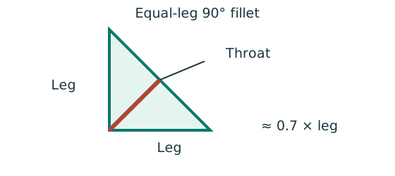
- For the stated equal-leg 90° fillet, throat is approximately 0.7 × leg.
- Multiply throat area by the matching weld design strength.
- For force per length, use a one-millimetre weld strip.
Remember: Choose strength from both the steel grade and electrode class.
The web weld meets the thicker-part minimum if the column flange thickness is at most under the supplied table. If it exceeds , the minimum would be , incompatible with the edge maximum in this edge-detail model; a different detail would be needed. Since column flange thickness is not stated, report as the completed strength selection with this explicit detailing condition, not an unconditional fabrication approval. Provide any required end returns of at least where the actual joint permits; their geometry is not dimensioned here.
Animation labFrom fillet leg to effective throat
Supplement to the original lesson. Enable JavaScript to play, step through calculations and rotate 3D models. The following explanation remains readable offline.
- An equal-leg fillet between perpendicular plates has an approximately right-triangular section.
- For this geometry, throat . It is shorter than the leg.
- Effective resisting area = . With here, capacity per length is .
- Use the course end allowances, minimum size and length rules; increasing the geometric length alone does not resolve every detailing check.
Compact exam answer
M150 kNm; source lever arm gives flange force . Use flange fillets on runs: effective , capacity each. For web shear use fillets on two runs: effective each, pair capacity 688.8 kN>600. Web minimum-size compliance remains conditional on the omitted column flange thickness ( selection permitted by the supplied minimum table only up to thicker part).
Mistakes to avoid
- Use the given weld run rather than nominal section width.
- Each flange carries the full couple force.
- Use both web runs for shear, but deduct from each.
- Do not claim an omitted column thickness has been checked.
Procedure for an unfamiliar variant
- Factor loads if required, then calculate .
- Convert moment into flange force using the stated force-couple model.
- Try flange leg sizes and update each effective length.
- Size the pair of web welds for the full shear force.
- Check known maximum/minimum size and length conditions; state missing detailing inputs.
Independent self-check
Try it yourself. Invented variant: ultimate load remains but its eccentricity rises to . Can the selected flange weld remain ?
Reveal answer and reasoning
, above the weld resistance . The web shear remains , so its strength demand is unchanged. A larger flange weld is limited by the edge maximum; even gives, still insufficient. A changed flange weld layout/detail is needed.
Animation labSeparate the moment couple and shear
Supplement to the original lesson. Enable JavaScript to play, step through calculations and rotate 3D models. The following explanation remains readable offline.
- A simplified moment connection assigns different actions to different fastener groups.
- Opposite flange forces separated by z resist moment: .
- The web fasteners or welds carry the assigned vertical shear in this model.
- Flange force, web shear, plate bearing and detailing each need their specified checks.