Assignment 1 Q2: a bolted splice
Open “Animation lab” beside a teaching step for a visual explanation or a walkthrough of its original expressions. Models are illustrative; source answers remain unchanged.
Need a simpler picture? Open “Simple explanation” beside a difficult step. These optional notes do not replace the full solution.
Check bolt shear, bolt bearing, plate bearing and plate tension for the source S355 splice: main plate, two covers, Grade 8.8 M30 bolts in holes, ultimate tension .
Original source: Assignment/AY2627s 1-CON4334-Assignment 1.pdf — p. 2. Values tagged given are in the question or diagram; lookup values come from a named table; calculated values follow from the working; assumptions are stated explicitly.
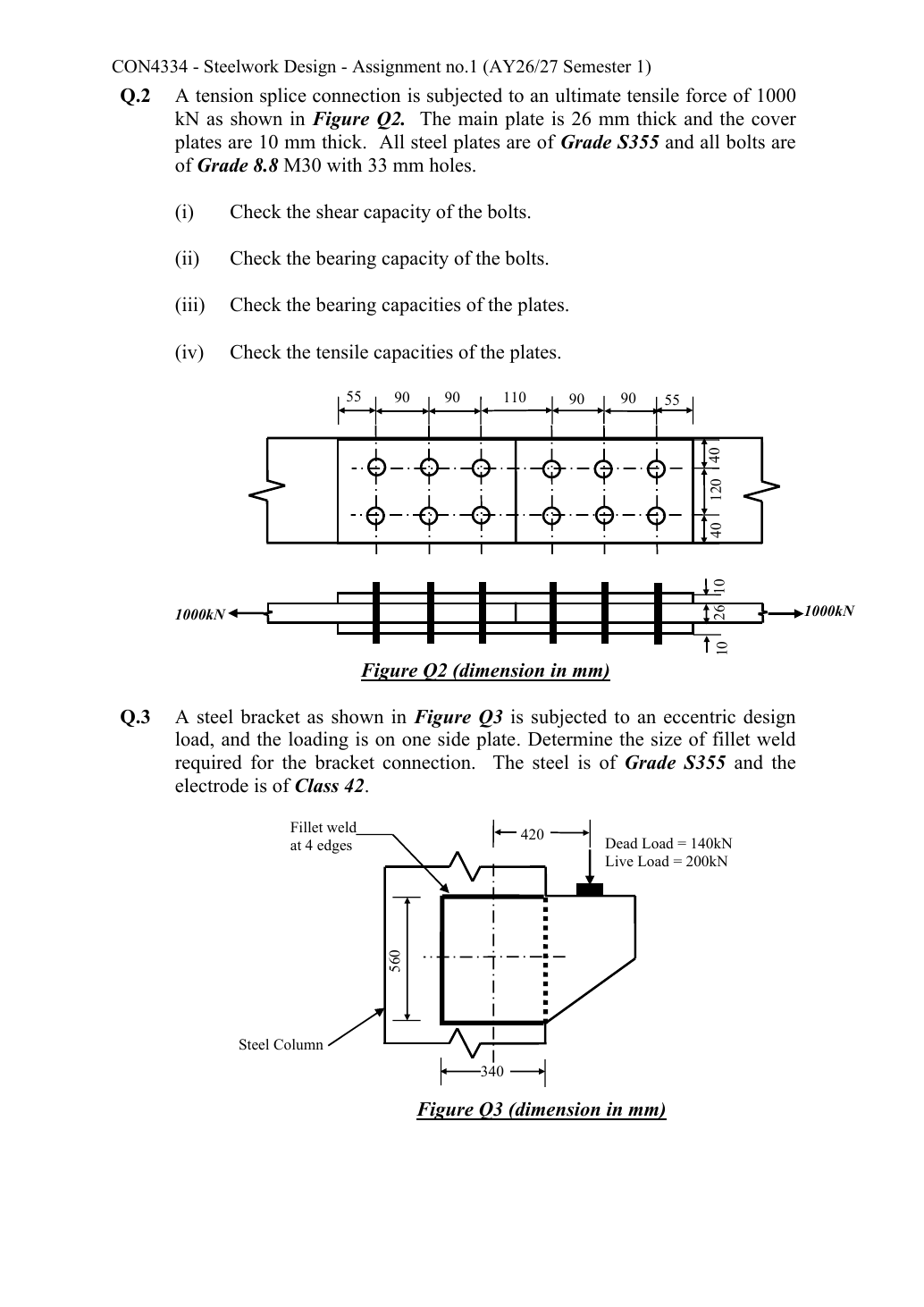
Read the diagram and collect the data
| Value | Origin/type |
|---|---|
| Tension | Given ultimate ; do not multiply by or . Each half-splice transfers this full force. |
| Fasteners | Given M30, Grade 8.8 and hole diameter . Ch 2 table: , , , . |
| Plates | Given S355; , . Main plate , giving ; cover plate , giving . |
| End distance | Cover end is explicitly dimensioned. For a numerical main-plate end check assume the butt lies centrally within the gap, e_m=; this split is a stated symmetry assumption, not a measured drawing length. |
| Distribution | Six bolts per half; main force/bolt ; each of two covers takes . |
Before calculating: recognition and strategy
Cut the joint at one half and follow force from the main plate through six double-shear bolts into the two covers. The other half performs the same transfer in reverse; twelve bolts are not one parallel group carrying . Check each material layer’s actual force and thickness, then the two-hole net section.
(i) Bolt shear capacity
Simple explanation: Count where the bolt can be sheared
The plate interfaces are the places trying to cut across the bolt.
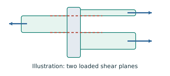
- Count actual loaded shear planes, not merely visible plates.
- Choose shank or threaded area for the plane concerned.
- Compare group resistance with the force that group transfers.
Remember: Bolts on opposite sides of a splice do not all act in parallel.
Using the threaded stress area is the conservative course model when thread location is not specified. Do not use the hole area as the bolt shear area.
Animation labCount the bolt shear planes
Supplement to the original lesson. Enable JavaScript to play, step through calculations and rotate 3D models. The following explanation remains readable offline.
- Load must cross an interface between the connected plates.
- A lap joint gives one shear plane through a bolt.
- A symmetric double-cover joint may provide two shear planes. Count load-transfer interfaces, not just visible plates.
- Use the source’s area and shear strength. Then check bearing, plate resistance and detailing separately.
(ii) Bolt bearing against all connected layers
Bolt bearing uses nominal bolt diameter and projected contact thickness. The bolt’s two cover contacts share the load; the thinner effective thickness is .
The is a bolt-material bearing limit. It is not the resistance of the weaker S355 plate material, which needs the next check.
Animation labBearing and the remaining ligament
Supplement to the original lesson. Enable JavaScript to play, step through calculations and rotate 3D models. The following explanation remains readable offline.
- Force transfers through contact between bolt and connected plate.
- The plate around the hole carries bearing stress. Bolt bearing and plate bearing are separate checks.
- A short ligament can tear out towards the end. The direction of force determines the relevant edge.
- Evaluate every specified bearing and ligament bound for each layer and retain the smallest applicable resistance.
(iii) Plate bearing and ligament limits
Simple explanation: The bolt can crush or tear the plate
A strong bolt can still push through a weak hole edge.
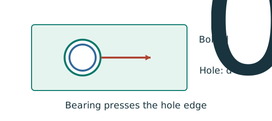
- Check the bolt and each connected plate’s bearing bounds.
- Use nominal bolt diameter for bearing; hole size for removed material.
- The smallest applicable resistance controls.
Remember: A short end distance may govern even when bolt shear passes.
Use Ch 2 pp.9–10: the ordinary, non-countersunk hole model uses ; nominal , longitudinal spacing , hole diameter , hence clear ligament between holes . For each plate, take the minimum of the three course bearing bounds.
| Bound per bolt | Main (e_m 55 assumed) | One cover (e 55 given) |
|---|---|---|
| ceiling | ||
| Minimum |
If the butt is not centered, retain the actual main end distancee_m. For the end-distance bearing bound alone:
This is only the strength-derived minimum; detailing may require substantially more. For a standard M30 bolt, the minimum end/edge distance is for a sheared or hand flame-cut edge, and for a rolled or machine gas-cut edge. The known transverse therefore satisfies the latter but not the former. The longitudinal spacing is ; transverse spacing ; maximum spacing , so the transverse spacing is exactly at the maximum. Confirm the edge preparation and the main-plate end distances on both sides of the butt joint before declaring the detail unconditionally satisfactory.
Animation labBearing and the remaining ligament
Supplement to the original lesson. Enable JavaScript to play, step through calculations and rotate 3D models. The following explanation remains readable offline.
- Force transfers through contact between bolt and connected plate.
- The plate around the hole carries bearing stress. Bolt bearing and plate bearing are separate checks.
- A short ligament can tear out towards the end. The direction of force determines the relevant edge.
- Evaluate every specified bearing and ligament bound for each layer and retain the smallest applicable resistance.
(iv) Main and cover tensile capacities
Simple explanation: Why holes reduce tension resistance
The pull must squeeze through the steel left beside the holes.
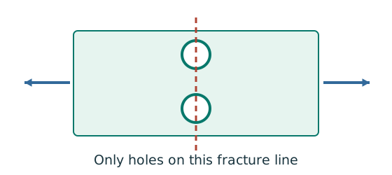
- Choose a possible fracture line across the member.
- Subtract the holes crossed by that line using hole diameter.
- Apply the course effective-area rule and its gross-area limit.
Remember: Do not subtract every hole anywhere in the connection.
A transverse net-section cut through an aligned bolt column crosses two holes, not all six holes along a half-splice. Course effective areaAe=min(Ag,KeAn), with Ke 1.1 for the stated S355 course model.
The cover pair’s tension resistance gives the smallest of the requested numerical group capacities. Strength passes under the stated end-bearing assumption, with only capacity above demand in cover tension. The transverse edge preparation caveat remains a separate detailing issue.
Animation labSubtract holes on the failure path
Supplement to the original lesson. Enable JavaScript to play, step through calculations and rotate 3D models. The following explanation remains readable offline.
- Gross area counts the complete plate width and thickness.
- The highlighted transverse path passes through the bolt holes.
- For the straight illustrative path, . Staggered paths require their specified correction.
- Net area is not always effective area. Include the course’s strength ratio or shear-lag rule when applicable.
Compact exam answer
Per half: sixM30 in double shear. Shear ; bolt bearing ; plate bearing main and cover pair (centered-butt e_m 55 assumed). Tensile main and cover pair . All exceed . Cover tension controls. side edges require an edge category permitting ; they fail the sheared-edge minimum. Confirm the main end-distance split before final approval.
Mistakes to avoid
- Do not divide by twelve bolts for a half-splice check.
- Do not add the full thickness for the controlling bolt bearing.
- Use for hole deductions and for projected bearing.
- Do not use in the main tensile calculation.
Procedure for an unfamiliar variant
- Draw the half-splice force path.
- Count shear planes and forces per plate.
- Check bolt shear and bearing.
- Evaluate every plate-bearing bound and detailing condition.
- Cut the correct net section, cap effective area at gross, and check main and covers separately.
Independent self-check
Try it yourself. Invented variant: ultimate tension increases to with no geometry change. Which demonstrated requested check first fails?
Reveal answer and reasoning
The cover-pair tensile resistance remains , below . The main tensile, shear and the stated bearing capacities still exceed , but any failed required check makes the detail inadequate. Cover tension cannot be rescued by surplus bolt shear resistance.