Tutorial 2 Q4: combined bolt shear and tension
Open “Animation lab” beside a teaching step for a visual explanation or a walkthrough of its original expressions. Models are illustrative; source answers remain unchanged.
Need a simpler picture? Open “Simple explanation” beside a difficult step. These optional notes do not replace the full solution.
Use the approximate method to check twelve Grade 8.8 M20 bolts in the bracket carrying characteristic dead and imposed at eccentricity .
Original source: LectureNotes/Ch 2_Connection.pdf — p. 45, p. 47. Values tagged given are in the question or diagram; lookup values come from a named table; calculated values follow from the working; assumptions are stated explicitly.
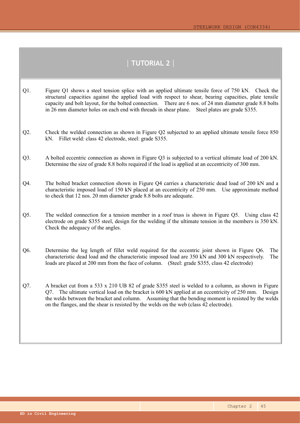
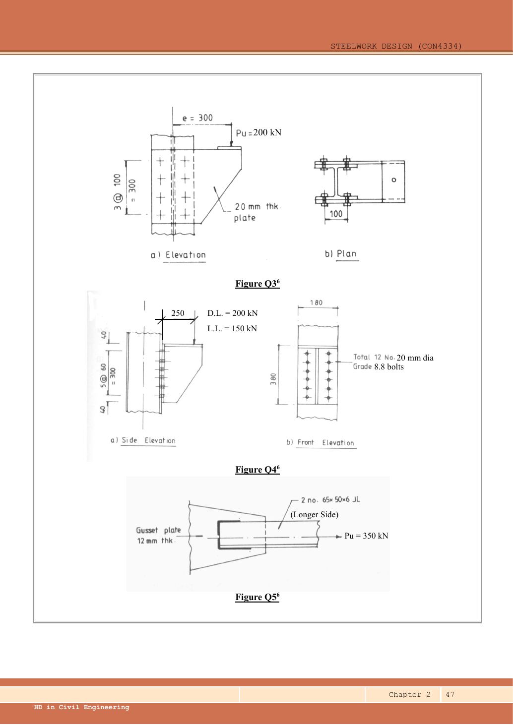
Read the diagram and collect the data
| Input | Origin/model |
|---|---|
| Loads | Given characteristic /; must be factored. |
| Approximate pivot | Follow the lecturer's lowest-bolt-row rotation model from connection example 4. Row distances are , with two bolts per row. |
| Fastener properties | M20 ,Grade 8.8 , ; nominal tension resistance . |
| Shear distribution | Equal direct shear over bolts; tension proportional to distance from the assumed pivot. |
Before calculating: recognition and strategy
The load acts out of the bolt-group plane and tends to peel the top of the plate away. The approximate method makes upper bolts carry more tension while every bolt carries direct shear. Even if each individual action is less than its own resistance, the combined interaction may fail. No official solution is supplied, so the wording “check that ... adequate” must not override the arithmetic.
1. Ultimate force, moment and maximum bolt tension
Simple explanation: Why the top bolt row is pulled hardest
The bracket tries to peel away from the support about the assumed contact line.
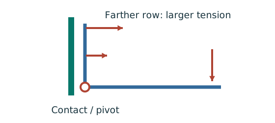
- Use the rotation/contact line assumed by the course model.
- Measure each bolt row’s distance from that line.
- Check maximum tension, direct shear and their interaction.
Remember: A row at the pivot can still carry direct shear.
The factor counts the two bolts at each row. The bottom row contributes zero to the assumed moment-resisting tension sum but still carries direct shear.
Animation labOut-of-plane bolt tension and prying
Supplement to the original lesson. Enable JavaScript to play, step through calculations and rotate 3D models. The following explanation remains readable offline.
- A bracket moment can create compression at the plate contact and tension in the bolt rows.
- The original assumed pivot/compression line determines each row distance.
- Under the elastic row model, a farther tension row attracts more tension. Direct shear may act simultaneously.
- Flexible plates can add prying force. Use nominal tension and interaction rules exactly as specified by the course.
2. Direct shear per bolt
Animation labCount the bolt shear planes
Supplement to the original lesson. Enable JavaScript to play, step through calculations and rotate 3D models. The following explanation remains readable offline.
- Load must cross an interface between the connected plates.
- A lap joint gives one shear plane through a bolt.
- A symmetric double-cover joint may provide two shear planes. Count load-transfer interfaces, not just visible plates.
- Use the source’s area and shear strength. Then check bearing, plate resistance and detailing separately.
3. Check the simultaneous actions on a top bolt
Simple explanation: Two passing checks may still interact
One bolt is doing two jobs at the same time.
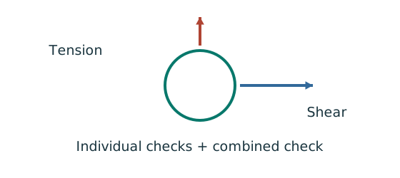
- Check shear on its own and tension on its own.
- Calculate the course’s combined-action expression.
- Apply its own limit, not a limit borrowed from columns.
Remember: The supplied bolt interaction limit of 1.4 does not replace the individual checks.
The course interaction limit is , as shown in Ch 2 p.10 and Example 4 p.28. Do not automatically use a limit of for every interaction equation. Both individual ratios are also below , so the requested approximate bolt strength check passes. The normalised combined utilisation is , a narrow margin. Gauge and supporting-flange dimensions are not supplied sufficiently to prove the no-prying condition or all bearing checks; the result is conditional on the course nominal-tension model being applicable.
The assumed rotation point is a modelling choice. If placed instead at the bottom contact edge below the lowest row, row distances become ,. Maximum tension becomes , with interaction approximately . This solution consistently uses the lecturer's lowest-bolt-row model.
Animation labCombined actions share resistance
Supplement to the original lesson. Enable JavaScript to play, step through calculations and rotate 3D models. The following explanation remains readable offline.
- Shear and tension, or compression and bending, must refer to the same bolt or checked section.
- Divide every action by the resistance prescribed for that term.
- The bars illustrate a linear sum only. Bolt interaction can have a different limit and individual checks; retain the original expression.
- A pass in one interaction does not prove all failure modes pass. Read the exact calculation in the source player below.
Compact exam answer
, . Lowest-row rotation point: ,. . M20 , . Individual checks pass; interaction . The given bolts satisfy the requested approximate shear/tension model. No-prying and bearing applicability still depends on unprovided support-detail information.
Mistakes to avoid
- Do not read “adequate” in the prompt as a required conclusion.
- Use twelve bolts for direct shear but the row-distance sum for tension.
- Do not compare only separate shear and tension results.
- A larger bolt requires new hole, spacing, edge and bearing checks.
Procedure for an unfamiliar variant
- Identify the force path and whether the joint is concentric, in-plane eccentric or out-of-plane eccentric.
- Read all dimensions from the relevant view; do not measure drawing scale.
- Distinguish characteristic from ultimate loads and factor only when needed.
- Calculate demand per fastener/weld with the appropriate equilibrium model.
- Check all requested resistances and detailing conditions separately.
- State whether the given detail passes, fails, or remains conditional on missing data.
Independent self-check
Try it yourself. Invented variant: with all geometry and the characteristic load ratio unchanged, what is the largest overall load multiplier that passes this interaction?
Reveal answer and reasoning
The interaction scales linearly with load. Its maximum multiplier=. Corresponding ultimate load=. Separate tension allows and shear allows , so combined action controls. This concerns the approximate bolt checks only and does not establish missing plate/bearing/no-prying conditions.
Animation labOut-of-plane bolt tension and prying
Supplement to the original lesson. Enable JavaScript to play, step through calculations and rotate 3D models. The following explanation remains readable offline.
- A bracket moment can create compression at the plate contact and tension in the bolt rows.
- The original assumed pivot/compression line determines each row distance.
- Under the elastic row model, a farther tension row attracts more tension. Direct shear may act simultaneously.
- Flexible plates can add prying force. Use nominal tension and interaction rules exactly as specified by the course.