Tutorial 2 Q5: double-angle weld design and a conflicting size rule
Open “Animation lab” beside a teaching step for a visual explanation or a walkthrough of its original expressions. Models are illustrative; source answers remain unchanged.
Need a simpler picture? Open “Simple explanation” beside a difficult step. These optional notes do not replace the full solution.
Design the welds for two unequal angles carrying ultimate tension, with their longer sides connected to a gusset. Use S355 and Class 42 electrode, and check angle tension resistance.
Original source: LectureNotes/Ch 2_Connection.pdf — p. 45, p. 47. Values tagged given are in the question or diagram; lookup values come from a named table; calculated values follow from the working; assumptions are stated explicitly.
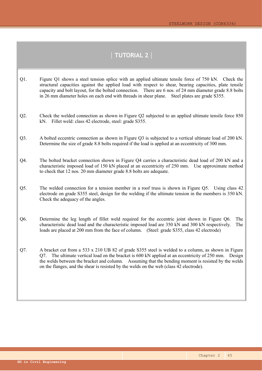
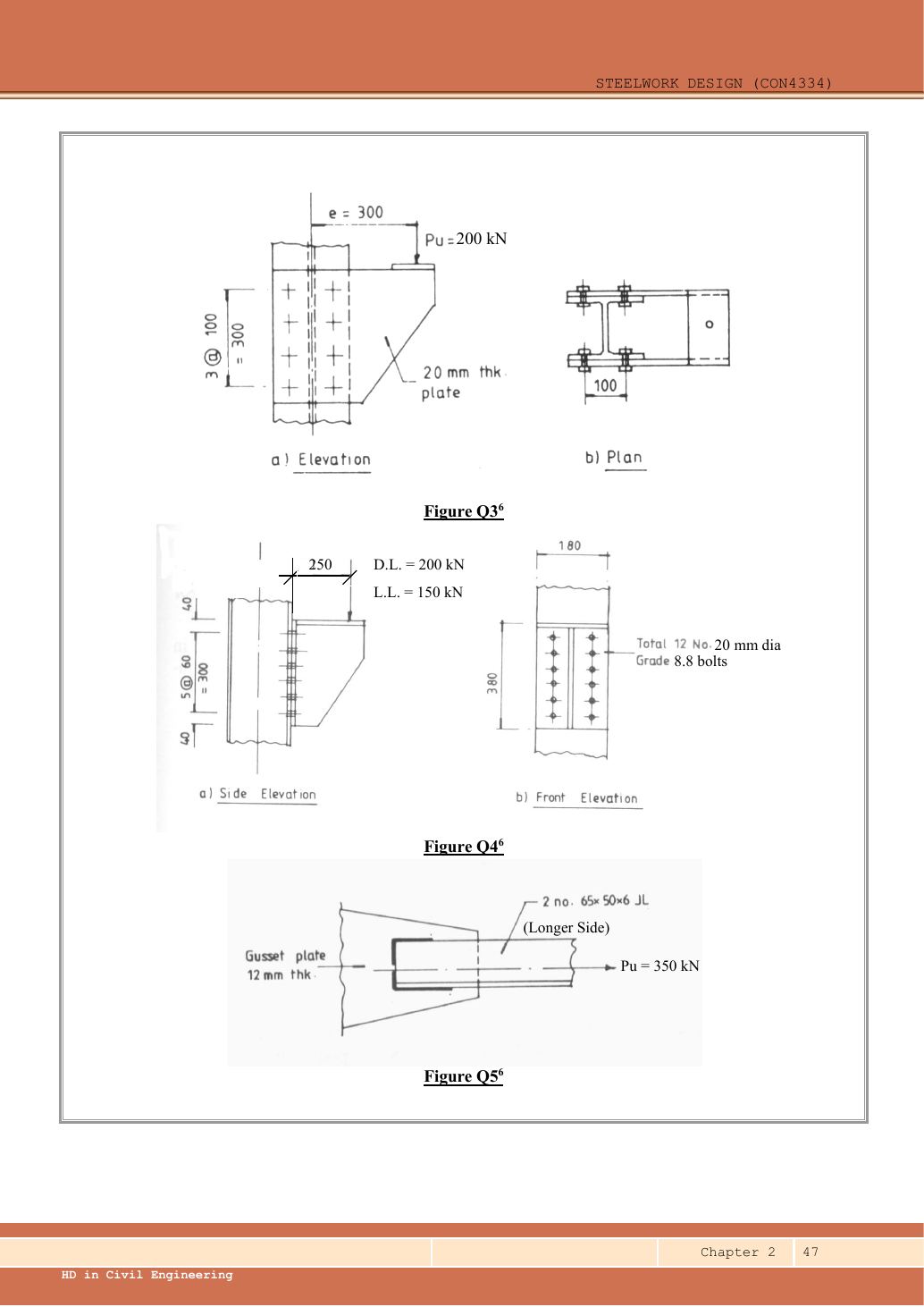
Read the diagram and collect the data
| Input | Source/type |
|---|---|
| Angle geometry | Given , two angles. For course rectangular leg areas split the shared corner equally between the two legs. |
| Centroid | Data File p.12, row, : measured from the heel along the long leg, while ; is the perpendicular coordinate. |
| Force share | Symmetric two-angle connection: each angle carries . |
| Weld resistance | The original website summary writes , whereas course weld calculations use ; this explanation explicitly uses the latter. For S355/Class 42, . The strength model uses only side welds and conservatively ignores the short transverse heel-end weld shown. |
| Size limits | Thicker joined part → source minimum ; angle edge → maximum . |
Before calculating: recognition and strategy
First check whether the angle pair can carry the force after the course shear-lag reduction. Then design unequal side-weld lengths so the weld resultant passes through each angle’s centroid. Finally check that the chosen leg is permitted by both minimum and maximum rules. In this particular detail those rules conflict; strength sizing alone cannot produce an acceptable final fillet-weld detail.
1. Check the two angles in tension
Simple explanation: One connected leg does not load both legs equally
The connected leg receives the pull first; the other leg receives it through the angle.
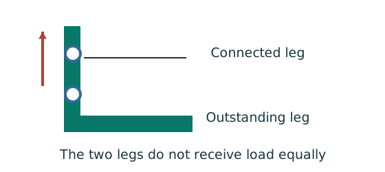
- Identify connected and outstanding legs from the drawing.
- Use the relevant bolted or welded angle rule.
- Keep the lecturer’s area convention consistent.
Remember: Bolted and welded reduction expressions are not the same rule.
The source section table gives rounded gross area including root/toe geometry. The course’s explicit leg-area model gives and is used consistently in this shear-lag calculation. Do not mix the table gross area with a different corner subtraction without explaining the method.
Animation labWhy a connected angle leg matters
Supplement to the original lesson. Enable JavaScript to play, step through calculations and rotate 3D models. The following explanation remains readable offline.
- Locate the connected leg, outstanding leg and centroid before using the table.
- Only the connected leg directly receives the fastener force.
- The outstanding area may not become equally effective at the same section; this motivates the effective-area rule.
- Bolted, welded, single-angle and double-angle details can have different rules. Preserve the formula attached to the original case.
2. Balance weld forces, then expose the detailing conflict
Simple explanation: Why two weld lengths can be unequal
Two side welds must balance the load about its actual line of action.
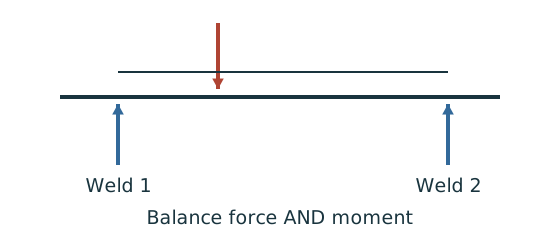
- Find the load line and the lever arm to each weld.
- Balance moments as well as the total force.
- Convert each weld’s force into its own required length.
Remember: Equal-looking legs do not justify equal weld forces without equilibrium.
Name the side nearer the angle heel and the free long-leg edge . Their transverse spacing is . The centroid is from and from . These are table-derived dimensions, not measured from the sketch.
For a transparent strength-only trial use fillet, the largest allowed by the source’s angle-edge maximum. This trial will be rejected on the minimum-size condition below.
Repeat on both angles. Effective lengths and 82 exceed and ; both physical lengths exceed the side spacing. Returns at least and lap at least would be required in such a trial.
Conclusion: the angles pass tension, but no fillet leg satisfies both supplied detailing rules for the stated angle/ gusset detail. The lengths / are a strength demonstration, not an acceptable final detail. A changed angle thickness or a separately justified alternative weld detail is required. The task cannot be concluded by silently adopting or along a angle edge. Gusset net width is not given, so a complete gusset tensile check also cannot be established.
Animation labBalance two weld forces
Supplement to the original lesson. Enable JavaScript to play, step through calculations and rotate 3D models. The following explanation remains readable offline.
- The angle centroid/load line is generally not halfway between the two weld runs.
- . Both weld runs contribute to the applied force.
- . The run nearer the load line carries more force.
- For equal throat resistance per length, the required effective lengths follow the same ratio. Add detailing allowances afterwards.
Compact exam answer
Double-angle tension resistance 434.307 kN>350. Per angle , centroid cₓ20.; side forces /. A4 mm strength-only side-weld trial needs / physical lengths. However the thicker part requires minimum while the edge permits maximum . No permissible fillet size exists under the supplied rules; revise the detail. Do not approve the strength-only trial.
Mistakes to avoid
- Use per angle, not 350 per angle.
- Use the long-leg centroid coordinate , not cᵧ.
- Use the double-angle welded reduction .
- Check whether minimum and maximum weld-leg bounds overlap before declaring a design.
Procedure for an unfamiliar variant
- Identify the connected leg and force per angle.
- Calculate the course angle tension area including the correct shear-lag reduction.
- Check the permitted weld-size interval.
- If a permissible size exists, balance side forces with centroid lever arms.
- Convert to effective lengths, add end allowances and check actual capacities/detailing.
Independent self-check
Try it yourself. Invented reasoning variant: would merely lengthening the welds solve the source minimum-leg problem?
Reveal answer and reasoning
No. More length increases strength but does not change the leg. The minimum remains . The physical detail/material choice or an explicitly supported alternative detailing provision must change.