Note: marks are as printed in the paper; the working is a teaching guide, not an official marking scheme.
Choose the column model first
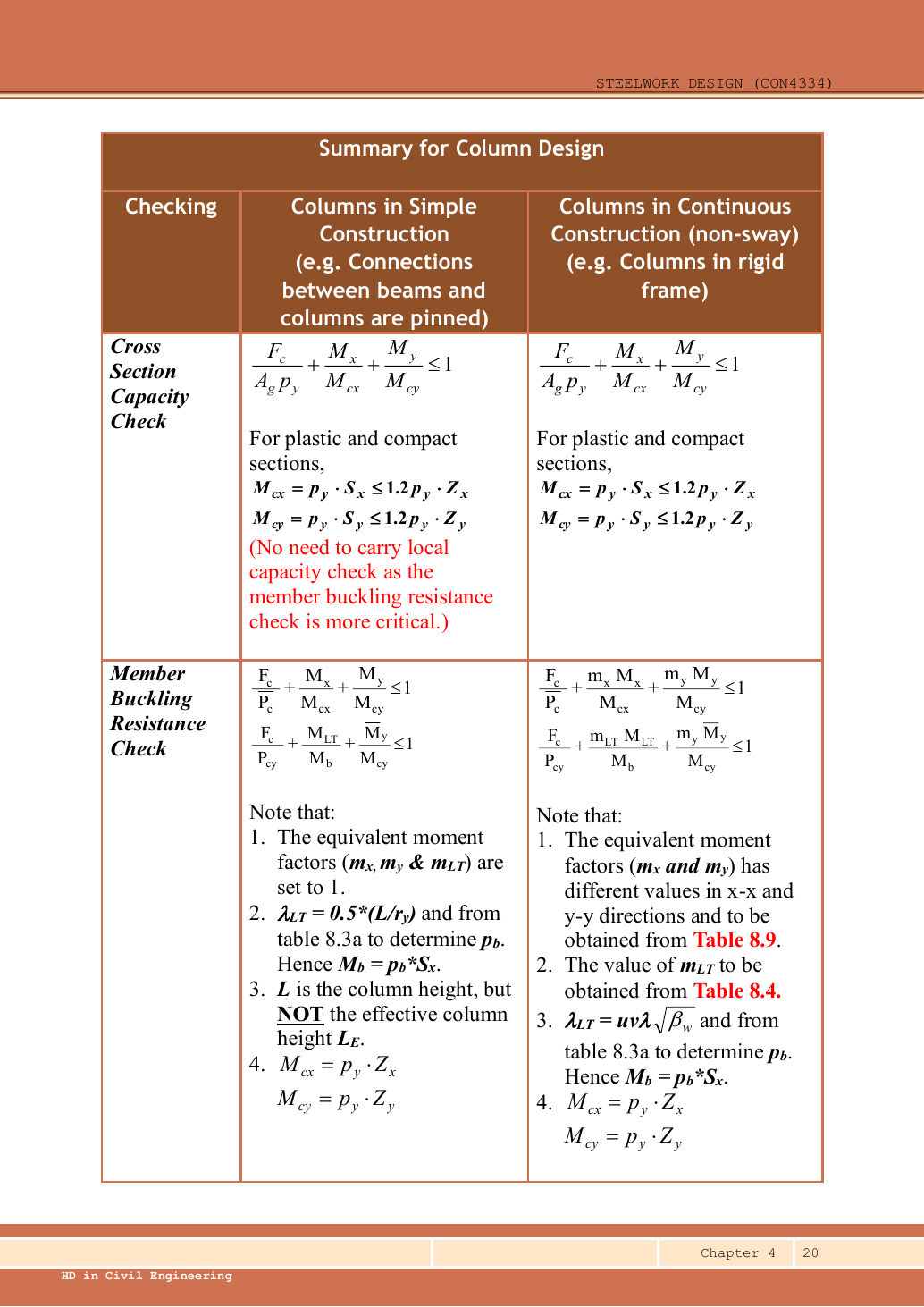
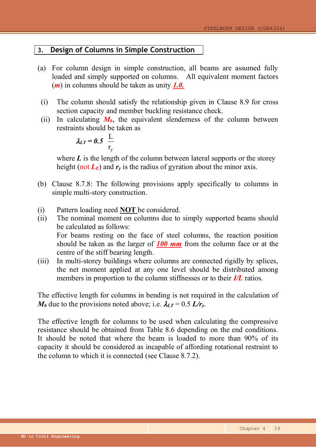
The 2022 and 2023 papers use the same 305 × 305 × 158 UC but give the moments in different ways. 2022: the end moments are given directly, with signs — use the continuous non-sway column method. 2023 (this page): beam reactions act off-centre at a joint — use the course’s simple-construction method, share the joint moment by stiffness, and use the moment factors the paper gives.
Simple explanation — open only if needed
A short steel block may survive squeezing while a long ruler with the same cross-section bends sideways. The section check asks whether the steel at one slice is strong enough. The member checks also ask whether the whole column can buckle. Passing one does not replace the others.
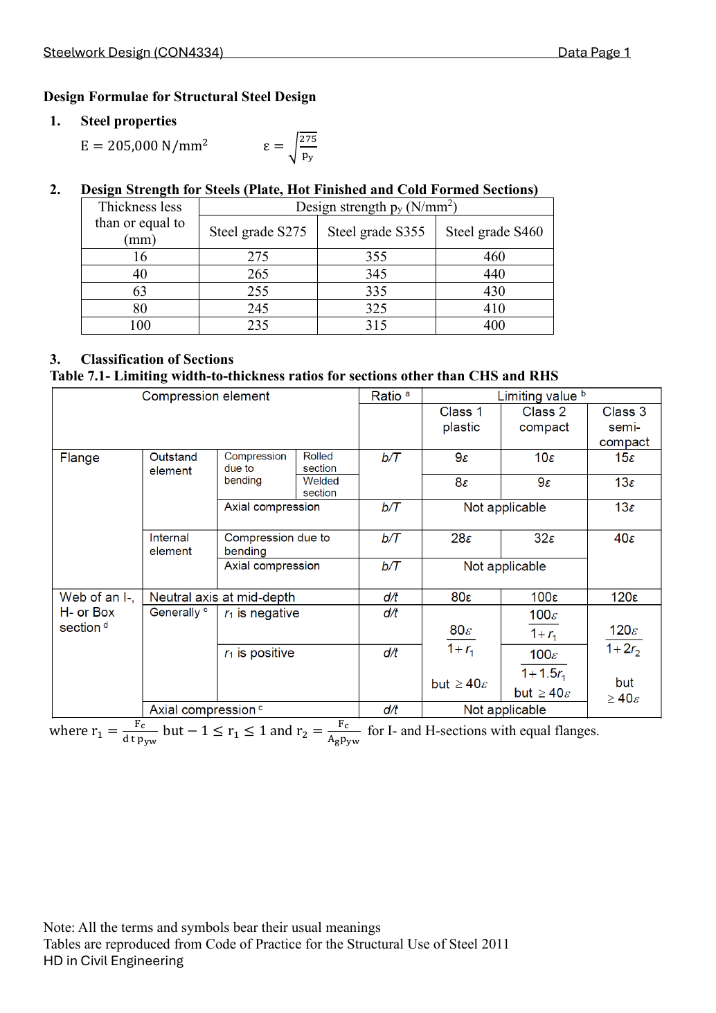
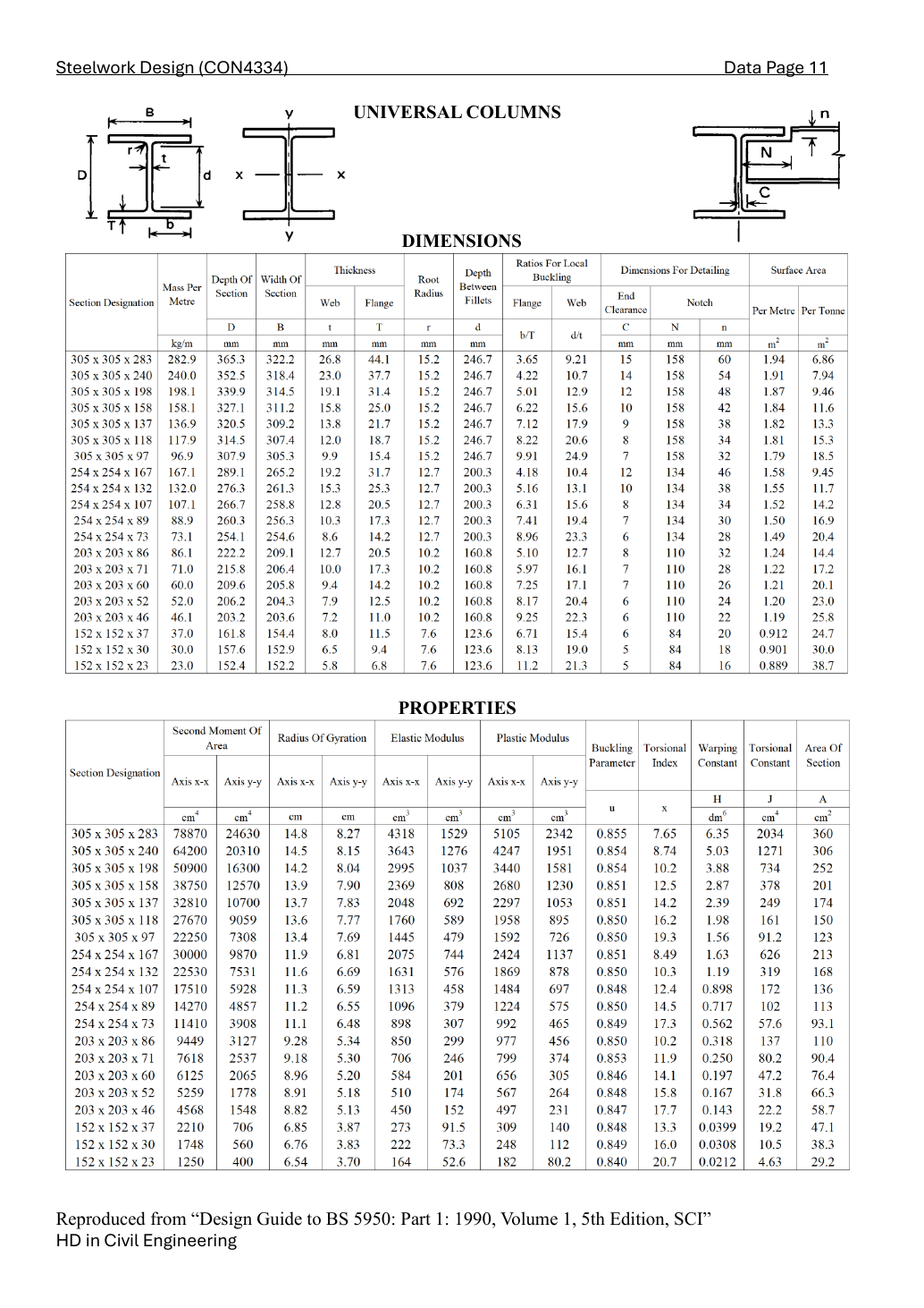
These are lookups from the exact UC row. The flange thickness selects the S355 design strength 345 N/mm². A is area, r radius of gyration, Z elastic modulus, S plastic modulus, T flange thickness and t web thickness. u and x are the LTB section parameters, not geometric coordinates.
BQ3(a) — axial force and moments [3 marks]
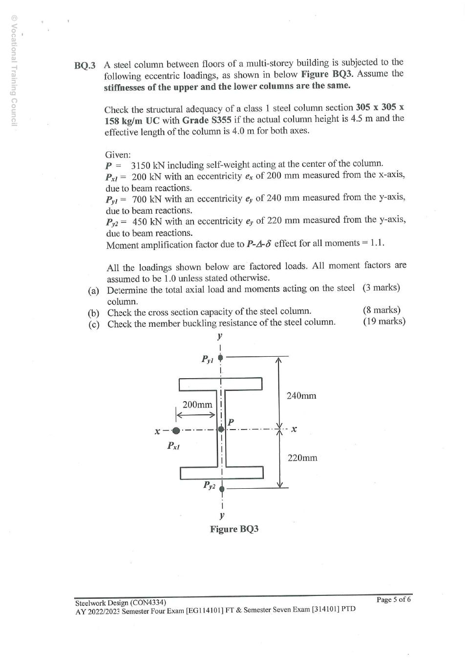
Given: central load 3,150 kN including self-weight; a 200 kN reaction at the left 200 mm offset, 700 kN above the centre at 240 mm and 450 kN below at 220 mm; all are already factored. Actual column height is 4.5 m; effective length is 4.0 m in both directions. Grade S355 and Class 1 are given. Upper and lower columns have equal stiffness; all moment factors are one and amplification is 1.1.
N=3150+200+700+450=4500kN
The top and bottom reactions rotate about x in opposite senses, so subtract their moment contributions. The left reaction contributes about y. Convert millimetres to metres for kN·m.
Mx,joint=700(0.240)−450(0.220)=168−99=69kNm
∣My,joint∣=200(0.200)=40kNm
Joint moment is shared in proportion to column stiffness. Equal upper/lower stiffness gives one half to the column under consideration. The axial force is not halved: the lower column carries the sum of the incoming vertical loads.
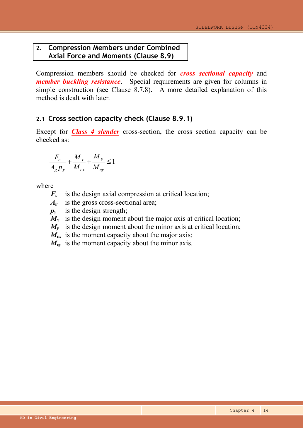
The cross-section check combines axial compression and two bending components at one section. Use amplified moments, gross compression resistance and the Class 1 capped plastic bending resistances. Every ratio must be dimensionless.
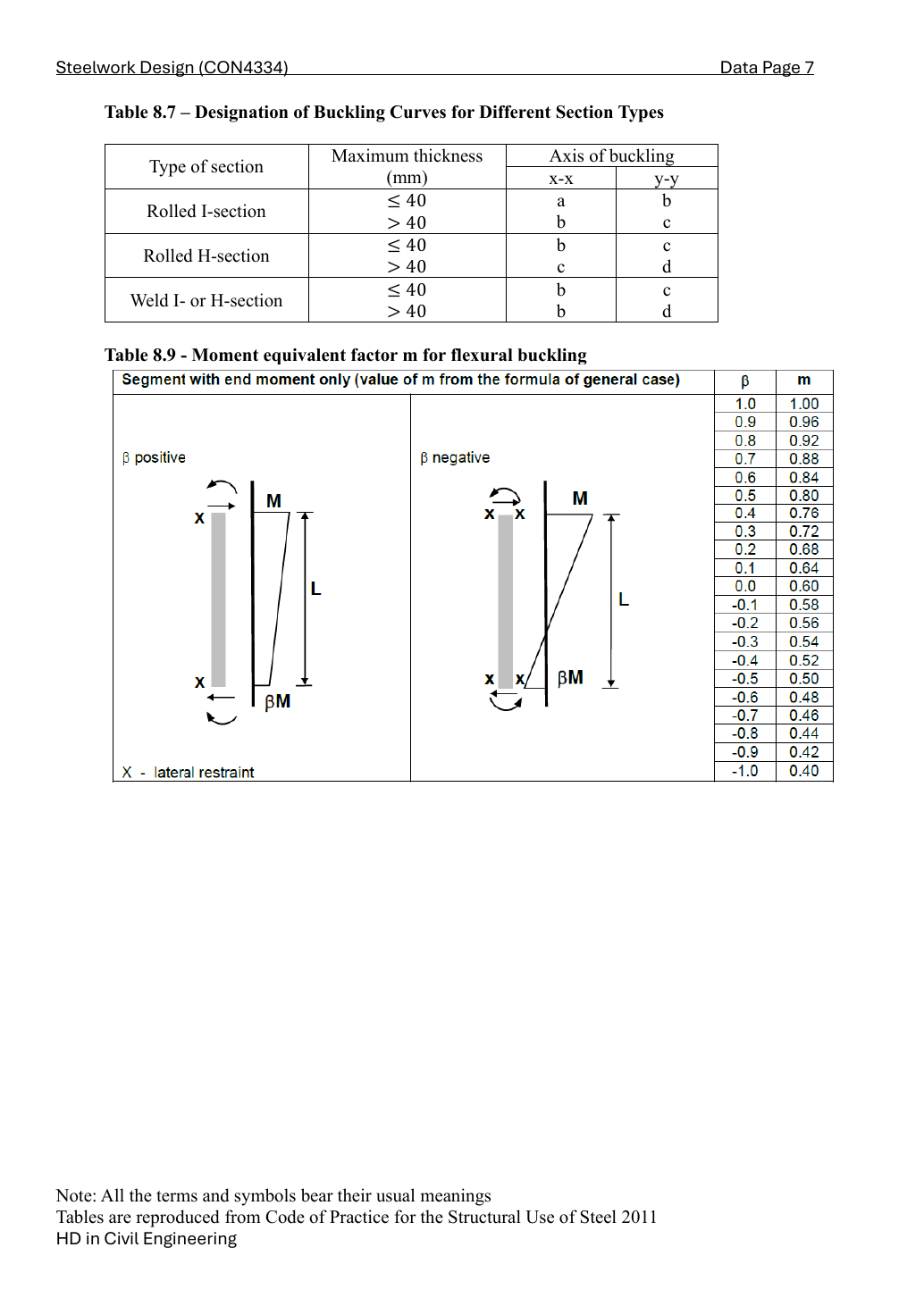
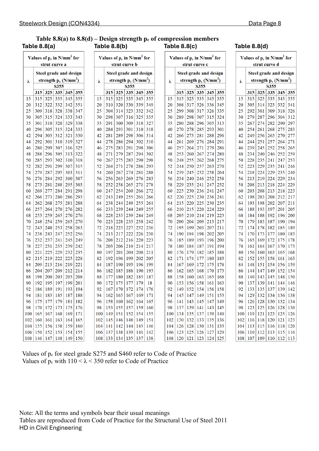
For the rolled UC with flange thickness below 40 mm, choose strut curve b about x and curve c about y. Effective length divided by the corresponding radius gives slenderness. Use the 345 N/mm² column of each curve’s compression-strength table.
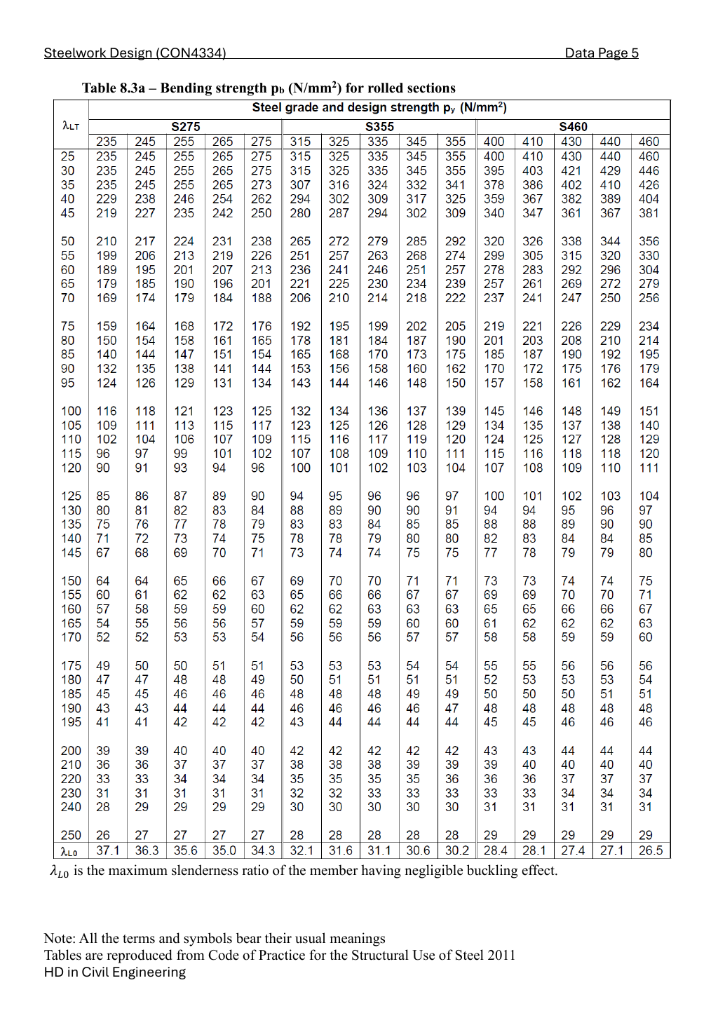
All three moment factors are given as one. The simple-construction LTB rule uses half the ACTUAL column height divided by the minor-axis radius. The 4,000 mm effective length belongs to compression slenderness, not this rule.
Choose Data File p.5, Table 8.3, 345 N/mm² column. Interpolate between the two surrounding slenderness rows in the same design-strength column; do not mix columns.
For the member interaction equations, the course uses ELASTIC section bending resistances. These are different from the capped plastic resistances used in the section check. The first member equation uses the smaller compression resistance and amplified moments.
The second member equation combines minor-axis compression buckling with major-axis LTB. It uses MLT as stated above and the first-order minor-axis moment (the barred moment in the course summary). Do not insert the amplified minor-axis moment again.