2024 BQ3: column class and all three combined-action checks
Open “Animation lab” beside a teaching step for a visual explanation or a walkthrough of its original expressions. Models are illustrative; source answers remain unchanged.
Need a simpler picture? Open “Simple explanation” beside a difficult step. These optional notes do not replace the full solution.
Answer all marks of BQ3. Check UC S355 with effective length and factored compression . Applied clockwise-positive top/bottom moments: -axis/; -axis/. Amplification factors /. The separately supplied amplified Mᴸᵀ is 96 kNm.
Original source: Pastpaper/23ENGTY004.pdf — p. 5. Values tagged given are in the question or diagram; lookup values come from a named table; calculated values follow from the working; assumptions are stated explicitly.
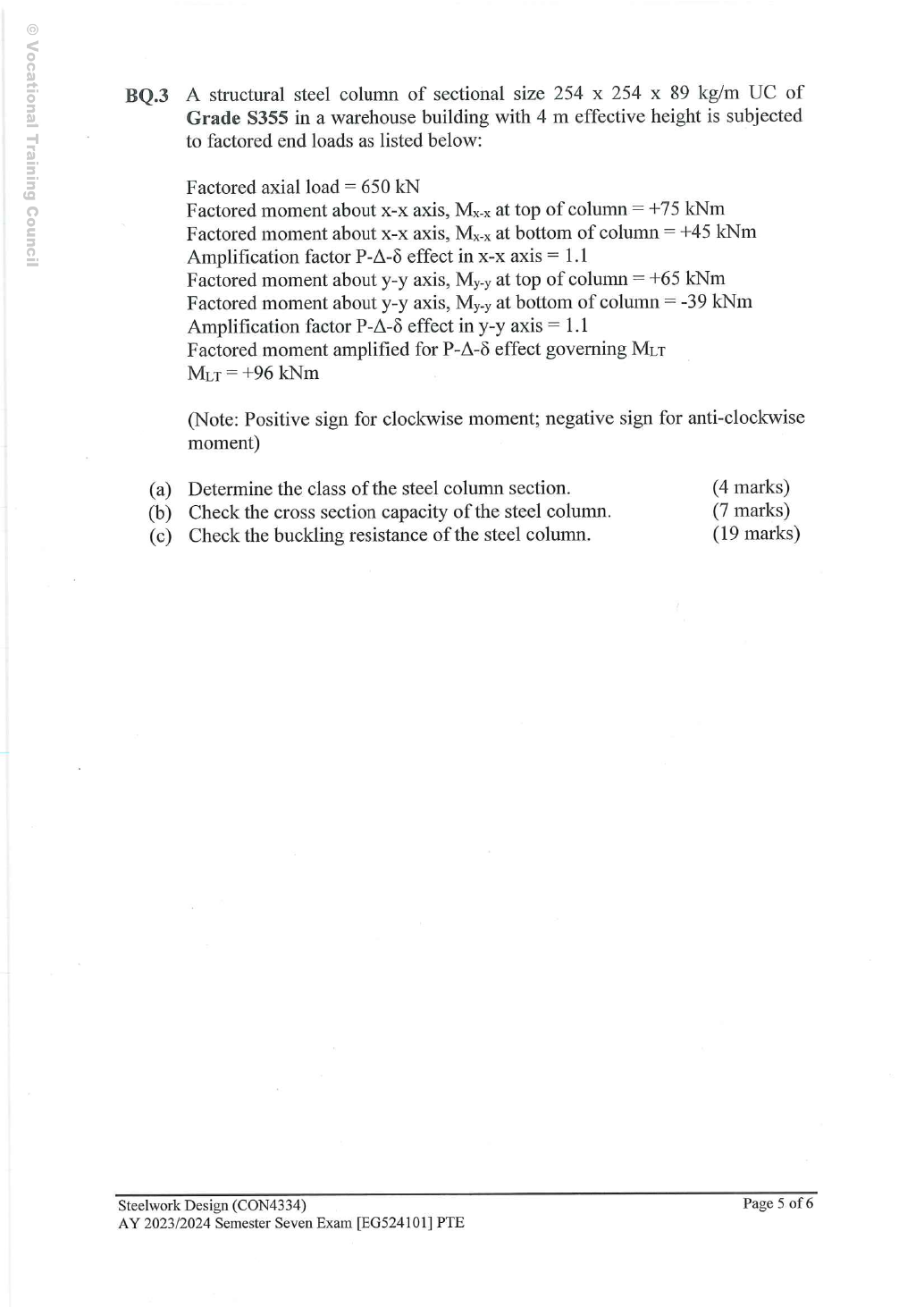
Read the diagram and collect the data
Lookup: Data File p.11, exact row UC. Read the dimensions/local ratios table and the properties table separately. The axis crosses the web horizontally; passes vertically through its centre in the table sketch.
| Property | Value and units |
|---|---|
| Flange/web/root-to-root web depth | 、、。 |
| Local slenderness | 、。 |
| Radii (converted from ) | ;。 |
| Area | 。 |
| Elastic moduli | ;。 |
| Plastic moduli | ;。 |
| LTB parameters | , ; both dimensionless |
Before calculating: recognition and strategy
The three checks answer different questions. Local classification determines the section resistance model. Cross-section interaction checks yielding/local resistance; flexural and axial/LTB interactions check member instability. Keep plastic versus elastic denominators and first-order versus amplified moments distinct. The top has both listed maximum moment magnitudes, so those maxima coexist.
(a) Classify the column section — 4 printed marks
Simple explanation: A thin part can wrinkle first
A thin plate may wrinkle before the whole steel member reaches its intended resistance.
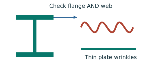
- Check flange and web slenderness using their own definitions.
- Compare each ratio with the correct class limits.
- The less favourable element determines the section class.
Remember: Bending limits and uniform-compression limits are different.
Web stress parameter: Using is capped to give . For any in this range, the conservative Class 1 web limit is . . The web satisfies this stricter limit. Overall Class 1; use capped plastic section resistance.
The lecture’s Class 1 combined-stress web limit cannot be below because . This check therefore avoids an unjustified plastic classification while remaining conservative. The flange is checked independently.
Use the flange’s Class 1 bound and the conservative combined-compression web bound explained above. The given compression affects web stress distribution but does not change the actual dimension ratios. The result is Class 1.
Animation labWhy thin elements buckle locally
Supplement to the original lesson. Enable JavaScript to play, step through calculations and rotate 3D models. The following explanation remains readable offline.
- The flange outstand and web have different widths, thicknesses and edge support conditions.
- A thinner plate can wrinkle locally before the complete member loses stability.
- Class 1 allows plastic rotation; Class 2 reaches plastic resistance; Class 3 reaches elastic resistance; Class 4 requires effective properties.
- Check every relevant compression element with the supplied limits and stress distribution. The deformation shown is qualitative.
(b) Cross-section capacity — 7 printed marks
Simple explanation: The column needs more than one pass
A slice can be strong while the whole member still buckles.
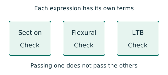
- Check cross-section compression plus bending.
- Then check the separate member-buckling expressions.
- Keep each moment, factor and resistance in its specified expression.
Remember: The three checks do not share interchangeable denominators.
At a cross section, compression and bending share the material. Use amplified moments and capped plastic resistances. The total must not exceed ; all terms below are dimensionless.
For this UC, the minor axis is governed by the cap. Using only would overestimate allowable minor-axis moment. The denominator of the section axial-force term is gross squash resistance , not member compression resistance .
Animation labA strong slice can belong to an unstable member
Supplement to the original lesson. Enable JavaScript to play, step through calculations and rotate 3D models. The following explanation remains readable offline.
- Combine axial compression and the two bending demands using the specified section resistances.
- The whole member adds effective-length and buckling-curve effects.
- This uses its own moment factor and bending resistance; it is not a copy of the section check.
- Elastic, plastic and buckling resistances are not interchangeable. Read the three original expressions and their first-order/amplified moments.
(c) Member buckling — 19 printed marks
Simple explanation: Why a long column can fail before crushing
Push a long thin ruler from both ends: it may bow sideways first.
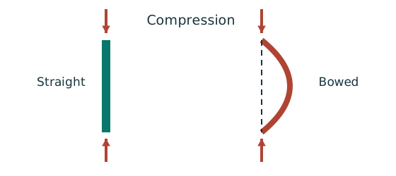
- Find effective length and radius of gyration for each axis.
- Calculate slenderness for both directions.
- Use the appropriate buckling curve before forming resistance.
Remember: Compare the final resistances; slenderness alone may not identify the controlling axis.
Simple explanation: A beam can escape sideways
The compressed flange can move sideways while the section twists.
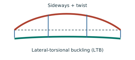
- Divide the beam at effective lateral restraints.
- Use each segment’s effective length to obtain its buckling resistance.
- Compare that resistance with the segment’s equivalent moment demand.
Remember: A section bending check alone does not check lateral-torsional buckling.
First read the factors from the two separate moment-gradient tables. The opposite-face convention makes internal for this clockwise-positive applied schedule.
Use the major-axis end pattern for the LTB moment factor in this course solution. The separate Mᴸᵀ magnitude must remain the value specified by the paper; do not replace it with the largest amplified simply because the values differ.
Table 8.7: hot-rolled H-section (UC), maximum thickness , about the axis use curve , about the axis use curve . Use the Data File p.8 column. The two axes use different curves, so slenderness alone cannot identify the governing axis.
Member interaction uses elastic moment denominators pᵧZ, even when the cross-section check used plastic moduli. Use amplified moments here.
Continuous/non-sway member: Class 1/2 gives . Use the full – calculation with the stated effective length.
Read Data File p.5 Table 8.3a, pᵧ345 column:
Course Eq.8.81 uses first-order minor-axis moment in its last term. Mᴸᵀ is the specified amplified major-axis value; do not amplify it twice. The axial denominator is .
; , ; , ; . Interaction ratios: section , flexural buckling , axial force/LTB . All three requested strength checks pass.
Suggested method-credit checkpoints (inferred, not an official allocation): correct strength/curve choice; both slendernesses; interpolation; correct signed factors; elastic member denominators; – calculation; both interaction ratios and a conclusion. Show these operations even if a final number differs slightly by rounding.
Animation labA strong slice can belong to an unstable member
Supplement to the original lesson. Enable JavaScript to play, step through calculations and rotate 3D models. The following explanation remains readable offline.
- Combine axial compression and the two bending demands using the specified section resistances.
- The whole member adds effective-length and buckling-curve effects.
- This uses its own moment factor and bending resistance; it is not a copy of the section check.
- Elastic, plastic and buckling resistances are not interchangeable. Read the three original expressions and their first-order/amplified moments.
Compact exam answer
(a) Class 1, pᵧ345. (b) amplifiedMx 82.5,My 71.5 kNm. (c) mx 0.480000,my 0.840000,mLT0.440000; givenMLT96 remains unchanged.
; , ; , ; . Interaction ratios: section , flexural buckling , axial force/LTB . All three requested strength checks pass.
Mistakes to avoid
- Do not apply an additionalK to the given effective height.
- Do not use the same end-moment factor formula for reversing flexural and LTB patterns.
- Do not amplify Mᴸᵀ twice.
- The final LTB minor-axis term uses the course first-order ; the flexural one uses amplifiedMy.
Procedure for an unfamiliar variant
- Read the sign convention and exact section row.
- Determine strength and class.
- Amplify each first-order moment once, preserving a separately given amplifiedMLT.
- Check the capped section resistances.
- Find both compression resistances and the signed moment factors.
- Complete flexural and axial/LTB interactions separately.
Independent self-check
Try it yourself. Invented variant: all first-order actions and the supplied amplifiedMᴸᵀ increase proportionally while section, effective length and amplification factors remain unchanged. What is the largest of the three new ratios?
Reveal answer and reasoning
With the same class and moment ratios, resistances/factors stay unchanged and all interaction demands scale by . The largest becomes . It remains below . Reconfirm classification after any changed axial load; the conservative web check here still covers boundedr₁.
Animation labA strong slice can belong to an unstable member
Supplement to the original lesson. Enable JavaScript to play, step through calculations and rotate 3D models. The following explanation remains readable offline.
- Combine axial compression and the two bending demands using the specified section resistances.
- The whole member adds effective-length and buckling-curve effects.
- This uses its own moment factor and bending resistance; it is not a copy of the section check.
- Elastic, plastic and buckling resistances are not interchangeable. Read the three original expressions and their first-order/amplified moments.