2022–2024 · Exam-focused route
2022 FT/PTDR — answer navigator
This is the paper dated 4 January 2022 (AY 2021/22).
Use the supplied exam format
Ask two separate design questions
Decide whether the check concerns failure or unacceptable behaviour during use.
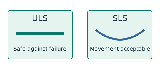
Prediction, then explanation. A larger section may improve both results, but a pass on one branch does not prove a pass on the other.
ULS addresses relevant strength and stability failure modes. SLS addresses specified service conditions such as deflection.
δ is the calculated displacement; δlimit is the permitted displacement. Both must use the same length unit.
Scope. Use each check’s own load combination and limit. A strength load factor does not change the physical stiffness.
Check and takeaway. Write separate conclusions for strength, stability and serviceability where requested. A single unexplained “safe” hides those distinctions.
Apply the reasoning to this section’s data and conditions
Two hours.
Section A is compulsory: 40 marks.
Choose any TWO of the three Section B questions, 30 marks each.
Answer 100 marks out of 130 offered.
These are printed allocations, not an invented marking scheme.
Suggested timing: 5 minutes to read and choose, 42 minutes for Section A.
Allow 32 minutes per chosen Section B question, 9 minutes to check.
Choose using the entire question, including the smaller subparts and missing assumptions.
Introduction / short theory
Delay heat reaching the steel
Identify how the protection surrounds a steel section. Then explain its purpose in a fire.
Prediction, then explanation. An insulating layer can slow heating. It does not mean the steel remains at room temperature indefinitely.
Heat changes steel behaviour. Protection delays that change by restricting heat transfer. Show the steel and protection boundaries separately.
The labelled boundaries describe geometry. They do not specify a tested fire-resistance rating.
Scope. Required thickness depends on the system, member and required rating. Do not infer thickness or minutes from a schematic.
Check and takeaway. For a sketch answer, distinguish all three shapes and state that protection delays steel heating.
Apply the reasoning to this section’s data and conditions
| Printed question / marks | Full solution | Status |
|---|---|---|
| AQ1(b) / 4 | AQ1(b) — two fire-protection methods | Checked within requested strength scope |
Connections
Count cuts through each loaded bolt
Find how many shear planes transfer the force through one side of the connection.
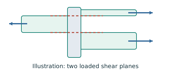
Prediction, then explanation. For equal sharing and unchanged bolt area, two active planes provide twice one plane’s shear resistance.
Select the area at the actual shear plane. Multiply by bolt shear strength. Count only the bolts and planes in the same transfer stage.
ps is bolt shear strength in N/mm²; As is the appropriate area in mm². nb counts bolts; ns counts equally loaded shear planes.
Scope. Use the thread area when threads cross the plane as required. Check bearing, plate failure and detailing separately.
Check and takeaway. Both halves of a butt splice carry the full transmitted force in sequence. Counting both halves together would double the apparent resistance.
Follow contact pressure into the plate
The bolt may survive shear while the connected plate deforms or tears near the hole.
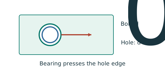
Prediction, then explanation. At fixed geometry and strength, a thicker plate raises plate resistance. Moving a hole too near the end can still govern.
Calculate every bound required by the supplied rule. The smallest applicable bound limits the connection at that layer.
pbs is the applicable bearing strength in N/mm²; d is nominal bolt diameter in mm; t is plate thickness in mm.
Scope. This diameter term alone is not the complete check. End-distance and clear-ligament limits, bolt bearing and each connected layer also matter.
Check and takeaway. Two covers and one main plate do not necessarily have the same thickness or strength. Compare the actual force share in each layer.
Test every possible fracture cut
Find the remaining steel area across a candidate tension-failure path.
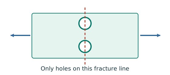
Prediction, then explanation. At fixed plate size, larger holes reduce the straight-path net area. A diagonal path needs its own stagger correction.
Subtract the hole widths crossed by the path, then multiply by thickness. Compare all plausible paths using the applicable course rule.
An is net area in mm²; b is plate width; d₀ is hole diameter; t is thickness, all in mm. n counts holes on this straight path.
Scope. This expression is for a straight cut. Effective area can require further shear-lag rules. Gross, net and effective areas must remain distinct.
Check and takeaway. Use the hole diameter, not the bolt diameter, when removing missing steel. The plate contains a hole, not solid steel around the bolt shank.
Apply the reasoning to this section’s data and conditions
| Printed question / marks | Full solution | Status |
|---|---|---|
| BQ1(a)(i) / 2 | BQ1(a)(i) — bolt shear | Checked within requested strength scope |
| BQ1(a)(ii) / 2 | BQ1(a)(ii) — bolt bearing | Checked within requested strength scope |
| BQ1(a)(iii) / 7 | BQ1(a)(iii) — plate bearing | Conditional — final adequacy incomplete |
| BQ1(a)(iv) / 5 | BQ1(a)(iv) — plate tension | Checked within requested strength scope |
| BQ1(b) / 14 | BQ1(b) — design the fillet weld | Conditional — final adequacy incomplete |
Beams, floor actions and LTB
Vertical bending can trigger sideways motion
A beam has enough local bending resistance. Check whether its compression flange can move sideways and twist.
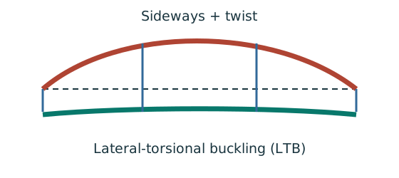
Prediction, then explanation. Adding a valid lateral restraint shortens a stability segment. It need not change the beam’s vertical reaction or moment diagram.
Identify the compressed flange and effective restraints. Calculate the specified slenderness, read buckling strength and compare resistance with the segment demand.
LE and ry use the same length unit. pb uses N/mm²; Sx uses mm³; Mb uses N·mm. mLT is dimensionless.
Scope. Use the specified section class, effective-length branch and loading condition. Load height alone does not prove a destabilizing case.
Check and takeaway. Removing a lateral restraint requires a new segment stability check. The old shorter-segment result cannot establish the longer segment’s adequacy.
Apply the reasoning to this section’s data and conditions
| Printed question / marks | Full solution | Status |
|---|---|---|
| AQ1(a)(i) / 4 | AQ1(a)(i) — slab design intensity | Checked within requested strength scope |
| AQ1(a)(ii) / 8 | AQ1(a)(ii) — actions on both beams | Conditional — final adequacy incomplete |
| AQ1(a)(iii) / 4 | AQ1(a)(iii) — classification | Checked within requested strength scope |
| AQ1(a)(iv) / 10 | AQ1(a)(iv) — B1 adequacy | Conditional — final adequacy incomplete |
| AQ1(a)(v) / 10 | AQ1(a)(v) — B2 adequacy | Conditional — final adequacy incomplete |
| BQ3(a) / 3 | BQ3(a) — support reactions | Checked within requested strength scope |
| BQ3(b) / 4 | BQ3(b) — annotated shear and moment diagrams | Checked within requested strength scope |
| BQ3(c) / 13 | BQ3(c) — segment BC | Conditional — final adequacy incomplete |
| BQ3(d) / 10 | BQ3(d) — segment CD | Conditional — final adequacy incomplete |
Columns
Find which plate buckles first
Before using plastic bending resistance, check whether the flange and web can sustain the required stress distribution.
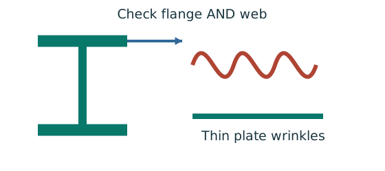
Prediction, then explanation. At fixed width, a thinner plate has a larger width-to-thickness ratio. Local buckling then becomes more restrictive.
Calculate the flange and web ratios separately. Compare each with the limits for its stress condition. The worse class governs.
py is the design yield strength in N/mm². ε is a dimensionless scale used in the supplied classification limits.
Scope. Pure bending and uniform compression use different web limits. Class 2 allows plastic resistance but not the Class 1 rotation capability.
Check and takeaway. A Class 1 web and Class 2 flange give a Class 2 section. Do not average the class numbers.
A strong cross-section can belong to an unstable member
A column carries axial compression and bending. Explain why more than one check is required.
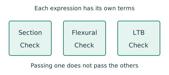
Prediction, then explanation. At fixed moments and resistances, increasing compression increases utilisation. A section pass cannot remove the length-dependent instability checks.
Separate cross-section, flexural-buckling and LTB interaction equations. Use each equation’s own denominators and first-order or amplified moments.
is a section axial resistance. is a member compression resistance. Elastic and prescribed are different bending denominators.
Scope. Preserve the course barred-moment definitions and Eq. 8.81 convention. Do not substitute plastic moduli into an elastic denominator.
Check and takeaway. Report each requested utilisation and the governing check. The largest properly calculated ratio identifies the closest limit.
Apply the reasoning to this section’s data and conditions
| Printed question / marks | Full solution | Status |
|---|---|---|
| BQ2(a) / 4 | BQ2(a) — section class | Conditional — final adequacy incomplete |
| BQ2(b) / 7 | BQ2(b) — cross-section capacity | Conditional — final adequacy incomplete |
| BQ2(c) / 19 | BQ2(c) — member buckling | Conditional — final adequacy incomplete |
All 18 printed subquestions have a worked teaching answer.
Conditional rows include the calculations and assumptions.