Two M20 bolts connecting an angle: link the checks (Bolted Angle)
Task: Check shear, bearing and angle tension, and understand how the smallest capacity governs.
Go straight to Step 1 ↓Design flow for this type of question: Ordinary bolted connection →
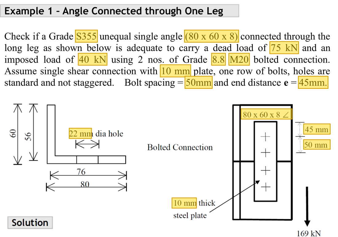
The question in short: 80×60×8 angle is fixed to a 10 mm plate by 2 M20 bolts in single shear. It is pulled by a dead load of 75 kN and an imposed load of 40 kN. Decide whether the bolts shear off, the hole walls crush, or the angle is pulled apart.
| Given | Value and Unit |
|---|---|
| Angle | 80×60×8, S355, connected through the long leg |
| Connecting plate | 10 mm thick |
| Bolts | Two Grade 8.8 M20 bolts in single shear |
| Holes and arrangement | ; pitch 50 mm; end distance 45 mm |
| Loading | Dead 75 kN; imposed 40 kN |
| Course strengths | ; ; ; ; |
| Shear area | per bolt |
Yellow: values given in the question. The same values are marked where they are substituted in the steps below.
Orange box: values read directly from the Data File, the same values boxed orange in the lookup screenshots. A value interpolated between two table rows is a calculation, so it has no box.
Solution Route: Calculate design force; check bolt shear, bolt bearing , thinner-plate bearing and angle effective-area tension in sequence. Finally check hole detailing separately.
This browser cannot show the 3D model.
The tension passes from the angle through the two bolts into the plate. Every station needs enough capacity; the weakest one decides the joint.
- Design tension
- Angle in tension (net section)Demand 169 kNCapacity 248.2 kNUtilisation 0.68
- Bearing on the 8 mm angleDemand 84.5 kNCapacity 88 kNper boltUtilisation 0.96 · closest to the limit
- Bolt shear (single shear)Demand 84.5 kNCapacity 91.875 kNper boltUtilisation 0.92
- 10 mm plateThicker than the angle, so the angle governs bearing
- Step 1 · Design force
Why this step: Real loads may be larger than expected, so they are scaled up by load factors first. Every later check uses this enlarged pull as the demand.
Both loads are unfactored. Use the lecturer's combination for this problem.
New symbols in this step- , , : Total force, shear per bolt and tension per bolt; kN
- , : Unfactored dead and imposed loads; kN
- Step 2 · Shear demand per bolt
Why this step: Capacity is worked out for one bolt, so the demand must also be the force on one bolt before the two can be compared.
Two bolts share the direct tensile force here, so each carries half the total.
New symbols in this step- , : Bolt spacing along the force, mm; number of bolts
Where the numbers come from: from Step 1.
- Step 3 · Shear resistance per bolt
Why this step: This guards against the bolt being cut across where the angle meets the plate. The result is the largest force one bolt can take before it shears off.
There is one shear plane. As is the effective area supplied in class, not the circular area of an M20 shank.
New symbols in this step- , , , : Shear, bolt bearing, plate bearing and plate tension resistances; kN
- , , , : Corresponding course design strengths; N/mm²
Units: is in N/mm² and is in mm², so their product is in N; dividing by 1000 gives kN.
Data file lookup · Data Page 4 · Bolt tables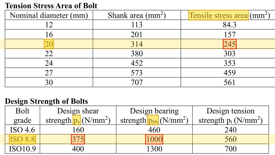
The M20 row gives tensile stress area ; the Grade 8.8 row gives and .Yellow: given parameter, row or columnOrange: value read from the table, boxed orange in the text too - Step 4 · Shear comparison
Why this step: Demand divided by capacity is the utilisation. Below 1 means the bolt will not shear off; the closer to 1, the less reserve is left.
84.5<91.875. Alternatively compare total capacity 183.75 with 169, keeping both sides at the same level.
- Step 5 · Select contact thickness
Why this step: The bolt shank presses on the hole wall, and the contact area is bolt diameter times plate thickness. This check guards against the bolt itself being crushed there.
The angle is 8 mm and the connecting plate 10 mm. Check the thinner 8 mm side first; with the same material and conditions it is less favourable.
Units: and are in mm and is in N/mm², so the product is in N; dividing by 1000 gives kN.
- Step 6 · Clear distance between holes
Why this step: is the steel actually left between two holes. If it is too short, the bolt can tear through it. The clear-distance limit in the next step uses it.
in plate bearing deducts hole diameter . Do not insert the 50 mm centre spacing directly.
New symbols in this step- , , , : Bolt diameter, hole diameter, end distance along force and clear hole spacing; mm
- Step 7 · Four plate-bearing bounds
Why this step: The four formulas stand for four ways to fail: hole wall crushed, plate end pushed out, steel between holes torn, and an upper limit tied to bolt strength.
For standard holes use and the 8 mm angle thickness. Calculate each bound and take the minimum.
New symbols in this step- , : Hole-type and effective-area factors; dimensionless
Where the numbers come from: from Step 6.
Units: , , and are in mm; , and are in N/mm². Each product is in N, and dividing by 1000 gives kN.
Data file lookup · Data Page 4 · Bearing of connected part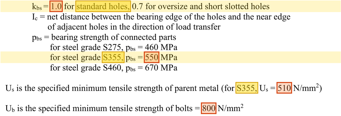
Standard holes give . For S355 plate the bearing strength is and ; for the bolt .Yellow: given parameter, row or columnOrange: value read from the table, boxed orange in the text too Load path · Four limits on plate bearingThe bolt presses on the hole wall, and the plate can fail in four ways: the hole wall crushes, the bolt tears out through the plate end, the plate tears between two holes, and there is a cap set by the bolt strength. The smallest of the four values is used (red frame). - Step 8 · Identify the governing bearing mode
Why this step: The smallest value comes from hole-wall crushing, so it decides the plate bearing capacity. Multiplied by the number of bolts, it can be compared with the whole design force.
88 comes from 20×8×550/1000. The others represent end distance , clear spacing and the bolt-strength cap. 88>84.5, but its margin is smaller than bolt shear's.
Where the numbers come from: from Step 7.
- Step 9 · Net area of the angle's connected leg
Why this step: The bolt hole removes steel, and the pull can only be carried by what is left beside the hole. So the leg with the hole uses the area after deducting the hole.
The drawing divides the angle along thickness centrelines. The long leg has geometric width 76 mm minus a 22 mm hole; the other leg is 56 mm wide.
New symbols in this step- , , : Gross and effective areas of the unconnected leg of the angle; is the gross area of the unconnected leg; mm²
- Step 10 · Effective-area cap
Why this step: The effective area is used for the capacity against the angle breaking at the hole. It cannot exceed the area without holes, since drilling a hole never adds steel.
Work each leg separately: multiply its net area by (1.1 for S355) to get its effective area , but must not exceed that leg's gross area. The unconnected leg has no hole, and 1.1×448=492.8 mm² exceeds its gross area, so 448 mm² is taken. Remark: the notes on screen in the recording multiply both legs together by 1.1, giving 968 mm² and ; the current lecture notes (Chapter 2, page 17) cap each leg, and answers should follow the current notes.
New symbols in this step- , , , : Bolt effective shear area and gross/net/effective plate areas; mm²
- , , : Gross, net and effective areas of the connected leg of the angle; mm²
Where the numbers come from: from Step 9; from Step 9.
Data file lookup · Data Page 2 · Tension members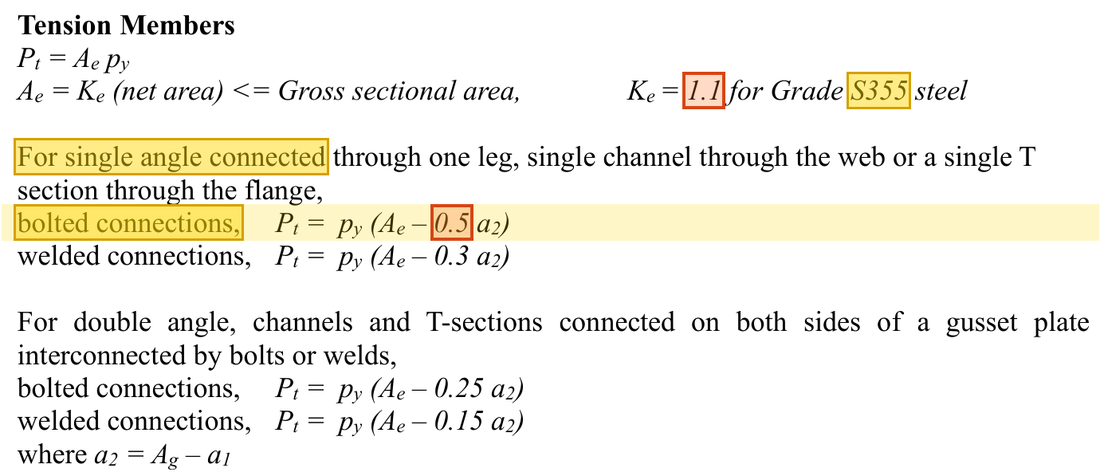
for S355; for a single angle bolted through one leg, .Yellow: given parameter, row or columnOrange: value read from the table, boxed orange in the text too - Step 11 · Single-leg connection reduction
Why this step: The pull enters on the bolted leg only, so the other leg works less. The formula therefore removes half the area of the unconnected leg, which lowers the capacity.
Force enters through only one leg. Use the lecturer's bolted single-leg expression rather than directly.
Where the numbers come from: from Step 10; from Step 9.
Units: is in N/mm² and the area in the brackets is in mm², so the product is in N; dividing by 1000 gives kN.
Data file lookup · Data Page 1 · Design strength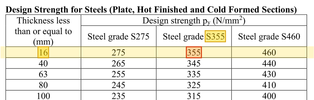
Angle 8 mm thick: the row, S355 column gives . How the grade and thickness choose this row →Yellow: given parameter, row or columnOrange: value read from the table, boxed orange in the text too - Step 12 · Overall interpretation
Why this step: A joint is like a chain: the weakest link fails first. Putting all the capacities side by side shows which one reaches its limit first.
Among these capacities, total angle-plate bearing of 176 kN is closest to 169 kN. The larger 248.2 kN is not the whole connection's sole resistance.
Calculated shear, bearing and angle-tension resistances all exceed 169 kN. All hole-position, edge-distance and other detailing requirements still need confirmation against the course tables.
All the symbols of this example
| Symbols | Meaning and Units |
|---|---|
| , , | Total force, shear per bolt and tension per bolt; kN |
| , , , | Shear, bolt bearing, plate bearing and plate tension resistances; kN |
| , , , | Bolt diameter, hole diameter, end distance along force and clear hole spacing; mm |
| , , , | Bolt effective shear area and gross/net/effective plate areas; mm² |
| , , | Gross, net and effective areas of the connected leg of the angle; mm² |
| , , | Gross and effective areas of the unconnected leg of the angle; is the gross area of the unconnected leg; mm² |
| , , , | Corresponding course design strengths; N/mm² |
| , | Plate and bolt ultimate tensile strengths; N/mm² |
| , | Hole-type and effective-area factors; dimensionless |
| , | Unfactored dead and imposed loads; kN |
| , | Bolt spacing along the force, mm; number of bolts |
Video positions: 19 September 02:10:00 · 19 September 02:12:30 · 19 September 02:05:00 · 19 September 02:55:00