Worked Example

Unrestrained B2: a strong section can still buckle (Unrestrained Beam)

Task: Connect the unfinished 17 October trial with the 24 October LTB result.

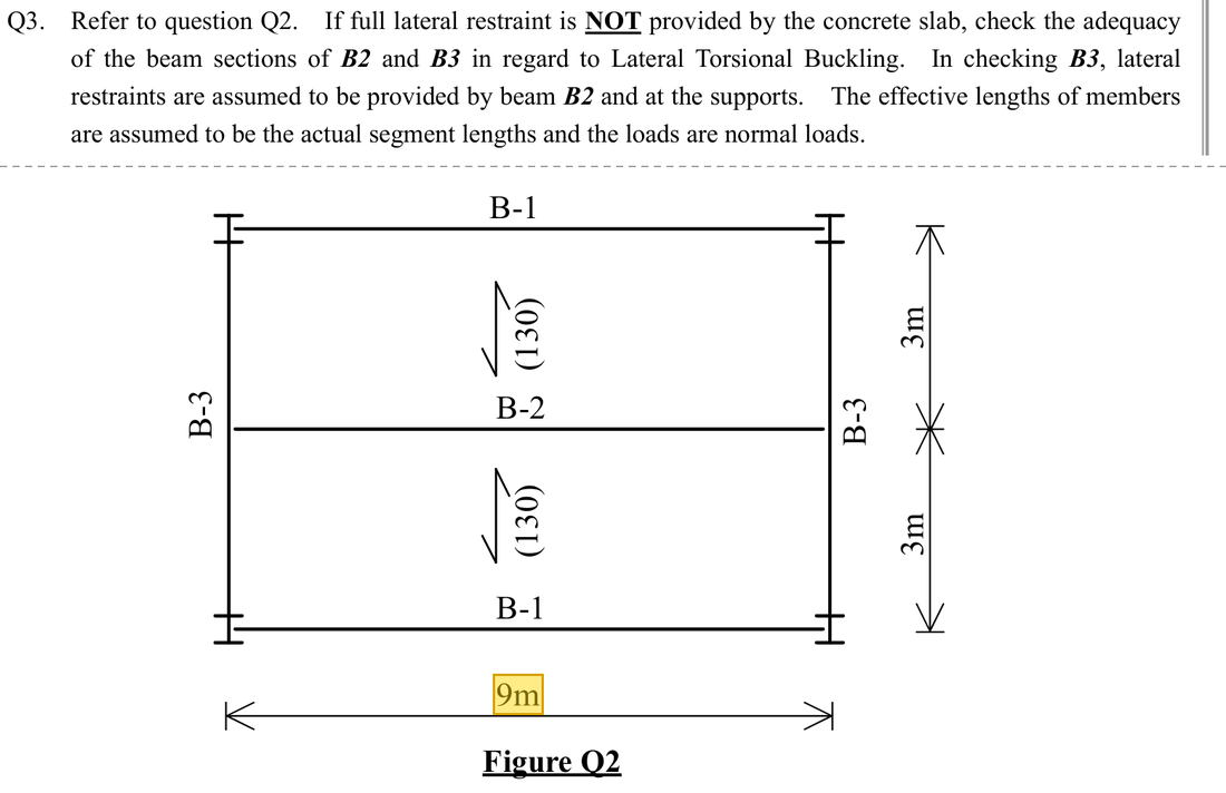
Original question · Lecture notes Chapter 3, p. 35–36 (Tutorial 3 Q3)
Original question with the given values boxed
Yellow boxes: values the question gives, the same values marked yellow in the Given table below.

The question in short: Beam B2 is a 457×191×67 UB. Nothing holds it sideways along its 9000 mm length. The largest moment is 492.48 kNm. Decide whether the beam will move sideways and twist (lateral-torsional buckling).

GivenValue and Unit
Effective lengthB2 (457×191×67 UB, S355) has no intermediate lateral restraint over the span; Le=9000 mm\htmlClass{given}{L_e=9000\ \mathrm{mm}}
Section parametersry=41.2 mm\htmlClass{read}{r_y=41.2\ \mathrm{mm}}; u=0.872\htmlClass{read}{u=0.872}; x=37.9\htmlClass{read}{x=37.9}; Sx=1471 cm3\htmlClass{read}{S_x=1471\ \mathrm{cm^{3}}}; py=355 N/mm2\htmlClass{read}{p_y=355\ \mathrm{N/mm^{2}}}
Bending momentMmax=492.48 kNm\htmlClass{given}{M_{max}=492.48\ \mathrm{kNm}} (B2 example); full-span UDL, mLT=0.93\htmlClass{read}{m_{LT}=0.93}

Yellow: values given in the question. The same values are marked where they are substituted in the steps below.
Orange box: values read directly from the Data File, the same values boxed orange in the lookup screenshots. A value interpolated between two table rows is a calculation, so it has no box.
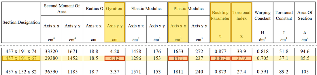
Data file lookup · Data Page 10 · Universal Beams — Properties
457×191×67 UB: ry = 4.12 cm = 41.2 mm, Sx = 1471 cm³, u = 0.872, x = 37.9.
457×191×67 UB: ry=4.12 cm=41.2 mmr_y=4.12\ \mathrm{cm}=41.2\ \mathrm{mm}, Sx=1471 cm3S_x=1471\ \mathrm{cm^{3}}, u=0.872u=0.872, x=37.9x=37.9.Yellow: given parameter, row or columnOrange: value read from the table, boxed orange in the text too

Solution Route: Confirm no intermediate restraint→convert to λLT\lambda_{LT} with course parameters→read pbp_b→calculate MbM_b→adjust demand.

Interactive 3D model · drag to turn

This browser cannot show the 3D model.

Drag the slider to see lateral-torsional buckling: with no intermediate restraint, the compressed top flange bows sideways over the whole 9 m and the section twists. The long effective length gives a large λLT\lambda_{LT}, so pbp_b is far below pyp_y; a strong enough section can still buckle.Yellow: values given in the question; orange box: values read from the Data File; white: calculated results; red arrows: forces.
Load path · the stations the force passes through, in order

The same B2: with no intermediate restraint, the compressed top flange is free to buckle sideways over the whole 9 m. A section strong enough in bending can still buckle first.

  1. Largest moment (midspan)
    492.48 kNm
  2. Unrestrained length
    Le=9000 mmL_e=9000\ \mathrm{mm}; λLT≈149.14\lambda_{LT}\approx149.14
    Step 1–2
  3. Buckling strength
    pb≈71.688 N/mm2p_b\approx71.688\ \mathrm{N/mm^{2}}, far below py=355p_y=355
    Step 3
  4. Lateral-torsional buckling (equivalent moment)
    Demand 458.0064 kNmCapacity 105.45 kNm
    Not enough: demand is 4.34 times the capacity
    Step 4–5
Each station links to the step that calculates it. Press “Show on the 3D model” to light up that part of the model above; press again to clear.
  1. Step 1 · Ordinary slenderness

    Why this step: Slenderness tells how long and thin the beam is between sideways supports. The larger it is, the more easily the compression flange moves sideways and the beam twists.

    Use mm consistently for LeL_e and ryr_y.

    New symbols in this step
    • LeL_e, ryr_y: Effective unrestrained length and weak-axis radius of gyration; both in mm
    • λ\lambda, λLT\lambda_{LT}: Ordinary and equivalent slenderness; dimensionless
    λ=LE/ry=9000/41.2≈218.45\lambda=L_E/r_y={\htmlClass{given}{9000}}/{\htmlClass{read}{41.2}}\approx218.45
    Load path · Load, shear force and bending moment
    Loads and reactionsw = 48.64 kN/mlateral restraintRA​ = 218.88 kNRB​ = 218.88 kN9 mBending moment diagram M (kNm): sagging moment drawn below the lineMmax​ = 492.48 kNmLE​ = 9000 mm, mLT​ = 0.93
    Here only the two ends are restrained laterally (green), so the top flange is free to buckle sideways over the whole 9 m. The moment diagram is a parabola, close to its maximum over most of the length, so mLT=0.93m_{LT}=0.93, near 1.

    ▶ The lecturer on this part: 24 October 00:09:47

  2. Step 2 · Do not use λ\lambda directly to read pbp_b

    Why this step: When the beam moves sideways it must also twist, and the section resists twisting. The factors uu and vv allow for this help, so λLT\lambda_{LT} is smaller than λ\lambda and suits the table.

    The lecturer obtains λLT≈149.14\lambda_{LT}\approx149.14. The original 218.45 is not the final table coordinate.

    New symbols in this step
    • uu, xx, vv, βw\beta_{w}: Course LTB section/conversion parameters; dimensionless
    v=[1+0.05(λ/x)2]−1/4=[1+0.05(218.45/37.9)2]−1/4≈0.783λLT=uvλβw=0.872(0.783)(218.45)≈149.14\begin{aligned}v&=\left[1+0.05(\lambda/x)^2\right]^{-1/4}\\&=\left[1+0.05(218.45/{\htmlClass{read}{37.9}})^2\right]^{-1/4}\approx0.783\\\lambda_{LT}&=uv\lambda\sqrt{\beta_w}={\htmlClass{read}{0.872}}(0.783)(218.45)\approx149.14\end{aligned}
    v=[1+0.05(λ/x)2]−1/4=[1+0.05(218.45/37.9)2]−1/4≈0.783λLT=uvλβw=0.872(0.783)(218.45)≈149.14\begin{aligned}v&=\left[1+0.05(\lambda/x)^2\right]^{-1/4}\\&=\left[1+0.05(218.45/{\htmlClass{read}{37.9}})^2\right]^{-1/4}\\&\approx0.783\\\lambda_{LT}&=uv\lambda\sqrt{\beta_w}\\&={\htmlClass{read}{0.872}}(0.783)(218.45)\\&\approx149.14\end{aligned}

    Where the numbers come from: 218.45218.45 from Step 1.

  3. Step 3 · Buckling resistance

    Why this step: pbp_b is the bending stress the beam can carry before it moves sideways and twists; it falls further below pyp_y as the beam gets more slender. Multiplying by SxS_x gives MbM_b, the moment the beam can carry before buckling.

    In the py=355p_y=355 column of Table 8.3a, λLT=149.14\lambda_{LT}=149.14 lies between the 145 and 150 rows; interpolation gives pb≈71.69 N/mm2p_b\approx71.69\ \mathrm{N/mm^{2}}, which is then multiplied by Sx=1471 cm3S_x=1471\ \mathrm{cm^{3}}.

    New symbols in this step
    • pyp_y, pbp_b: Design yield and bending buckling strengths; N/mm²
    • λ1\lambda_1, λ2\lambda_2, p1p_1, p2p_2: Slenderness and table values of the two rows used for interpolation
    pb=p1+λLT−λ1λ2−λ1(p2−p1)=75+149.14−145150−145(71−75)≈71.688 N/mm2Mb=pbSx=71.688(1471)/1000≈105.45 kNm\begin{aligned}p_b&=p_1+\frac{\lambda_{LT}-\lambda_1}{\lambda_2-\lambda_1}(p_2-p_1)\\&={\htmlClass{read}{75}}+\frac{149.14-{\htmlClass{given}{145}}}{{\htmlClass{given}{150}}-{\htmlClass{given}{145}}}({\htmlClass{read}{71}}-{\htmlClass{read}{75}})\approx71.688\ \mathrm{N/mm^2}\\M_b&=p_bS_x=71.688({\htmlClass{read}{1471}})/1000\approx105.45\ \mathrm{kNm}\end{aligned}
    pb=p1+λLT−λ1λ2−λ1(p2−p1)=75+149.14−145150−145(71−75)≈71.688 N/mm2Mb=pbSx=71.688(1471)/1000≈105.45 kNm\begin{aligned}p_b&=p_1+\frac{\lambda_{LT}-\lambda_1}{\lambda_2-\lambda_1}(p_2-p_1)\\&={\htmlClass{read}{75}}+\frac{149.14-{\htmlClass{given}{145}}}{{\htmlClass{given}{150}}-{\htmlClass{given}{145}}}({\htmlClass{read}{71}}-{\htmlClass{read}{75}})\\&\approx71.688\ \mathrm{N/mm^2}\\M_b&=p_bS_x\\&=71.688({\htmlClass{read}{1471}})/1000\\&\approx105.45\ \mathrm{kNm}\end{aligned}

    Where the numbers come from: 149.14149.14 from Step 2.

    Units: SxS_x is in cm³, and 1 cm³ = 1000 mm³. N/mm² times mm³ gives Nmm; dividing by 1000000 gives kNm. Together the two steps are a division by 1000.

    Data file lookup · Data Page 5 · Table 8.3a
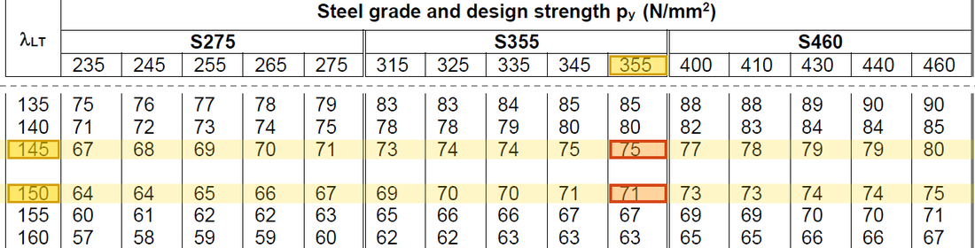
    Table 8.3a, py = 355 column: λLT = 145 → 75 and λLT = 150 → 71 N/mm²; interpolating at λLT = 149.14 gives pb ≈ 71.69 N/mm².
    Table 8.3a, py=355p_y=355 column: λLT=145\lambda_{LT}=145 → 75 and λLT=150\lambda_{LT}=150 → 71 N/mm²; interpolating at λLT=149.14\lambda_{LT}=149.14 gives pb≈71.69 N/mm2p_b\approx71.69\ \mathrm{N/mm^{2}}.Yellow: given parameter, row or columnOrange: value read from the table, boxed orange in the text too
  4. Step 4 · Equivalent demand

    Why this step: The table capacity assumes the same moment along the whole length. In fact the largest moment occurs at one place only and is smaller elsewhere, so mLTm_{LT} lowers the demand a little.

    The segment UDL moment diagram gives mLT=0.93m_{LT}=0.93.

    New symbols in this step
    • β\beta, mLTm_{LT}: Moment-diagram ratio and equivalent moment factor; dimensionless
    • M2M_2, M3M_3, M4M_4, MmaxM_{max}: Quarter-point and maximum moments from the same load case; kNm
    Meq=mLTMmax=0.93(492.48)=458.0064 kNmM_{eq}=m_{LT}M_{max}={\htmlClass{read}{0.93}}({\htmlClass{given}{492.48}})=458.0064\ \mathrm{kNm}
    Meq=mLTMmax=0.93(492.48)=458.0064 kNm\begin{aligned}M_{eq}&=m_{LT}M_{max}\\&={\htmlClass{read}{0.93}}({\htmlClass{given}{492.48}})\\&=458.0064\ \mathrm{kNm}\end{aligned}
    Data file lookup · Data Page 6 · Table 8.4a special case
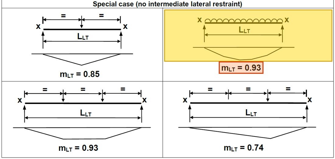
    Table 8.4a special case: no intermediate lateral restraint and a UDL over the whole length, mLT = 0.93.
    Table 8.4a special case: no intermediate lateral restraint and a UDL over the whole length, mLT=0.93m_{LT}=0.93.Yellow: given parameter, row or columnOrange: value read from the table, boxed orange in the text too

    ▶ The lecturer on this part: 24 October 00:14:31

  5. Step 5 · Comparison

    Why this step: A ratio above 1 means the beam moves sideways and twists before the section itself fails in bending. This is a different way of failing from the section bending check.

    Comparing in kNm shows a substantial resistance shortfall.

    New symbols in this step
    • SxS_x, MbM_b: Plastic modulus cm³ or mm³; LTB resistance kNm
    ηLTB=Meq/Mb=458.0064/105.45≈4.34>1\eta_{LTB}=M_{eq}/M_b=458.0064/105.45\approx4.34>1
    ηLTB=Meq/Mb=458.0064/105.45≈4.34>1\begin{aligned}\eta_{LTB}&=M_{eq}/M_b\\&=458.0064/105.45\\&\approx4.34\\&>1\end{aligned}

    Where the numbers come from: 458.0064458.0064 from Step 4; 105.45105.45 from Step 3.

    ▶ The lecturer on this part: 24 October 00:09:47

Conclusion

This unrestrained case fails LTB. The earlier satisfactory section-bending check concerns another failure mode. Lateral restraints or a larger section may improve it, but any change requires recalculation.

All the symbols of this example

SymbolsMeaning and Units
LeL_e, ryr_yEffective unrestrained length and weak-axis radius of gyration; both in mm
λ\lambda, λLT\lambda_{LT}Ordinary and equivalent slenderness; dimensionless
uu, xx, vv, βw\beta_{w}Course LTB section/conversion parameters; dimensionless
pyp_y, pbp_bDesign yield and bending buckling strengths; N/mm²
SxS_x, MbM_bPlastic modulus cm³ or mm³; LTB resistance kNm
β\beta, mLTm_{LT}Moment-diagram ratio and equivalent moment factor; dimensionless
M2M_2, M3M_3, M4M_4, MmaxM_{max}Quarter-point and maximum moments from the same load case; kNm
λ1\lambda_1, λ2\lambda_2, p1p_1, p2p_2Slenderness and table values of the two rows used for interpolation

Video positions: 17 October 02:50:00 · 24 October 00:10:00

↑ Top