Test and connection revision: double-cover bolted splices
This recording contains the 960 kN test and a replay of the old 750 kN example. They look similar but differ in plate thickness, bolts, holes and loading. Identify the problem before following the four checks. The lecturer gives no complete 960 kN solution; this page completes it using the course method.
Abbreviations: DL—Dead Load; LL—Live Load; ULS—Ultimate Limit State; SLS—Serviceability Limit State; UDL—Uniformly Distributed Load; LTB—Lateral-torsional Buckling; UB—Universal Beam; UC—Universal Column.
Key Points
- In a double-cover splice, each half-joint transmits the full axial force; each bolt has two shear planes.
- Four checks: bolt shear, bolt bearing , plate bearing and plate tension.
- For bearing thickness, compare the central main plate with the combined thickness of both covers and take the smaller.
- Net section deducts hole diameter , not bolt diameter .
- Thinner covers may have tension resistance closer to demand than the main plate.
Key Formulas
Exam Question Types
- 960 kN test: all four checks. → 960 kN test question: four checks (Four Checks)
- Replay of the 750 kN example. → 750 kN double-cover splice: separate capacity and spacing (Double-cover Splice)
Design flows for these question types
- The test period after 01:25 has been omitted.
- For the replay of 19 September during this class, screenshots use the clearer original 19 September recording.
- The lecturer does not publish a complete solution to the 960 kN test. This page calculates it using the taught method.
Establish the test's given data first (Test Data)
What this unit is for: A splice question involves three things, the main plate, the cover plates and the bolts; this unit first gets the sizes, materials and load of the question written down correctly.
Picture it this way: Picture a sandwich biscuit: the thick middle layer is the main plate, the two thin outer layers are the cover plates, and the bolts pass through all three. The pull goes from the middle layer through the bolts into the outer layers. Plates and bolts have their own strengths, and a load already given as ultimate is not factored again.
Prerequisites: Several failure paths in a bolted connection (Bolted Connections) · Use units to identify what you are calculating (Units and Dimensions) · When to check strength and when to check deformation (Limit States)
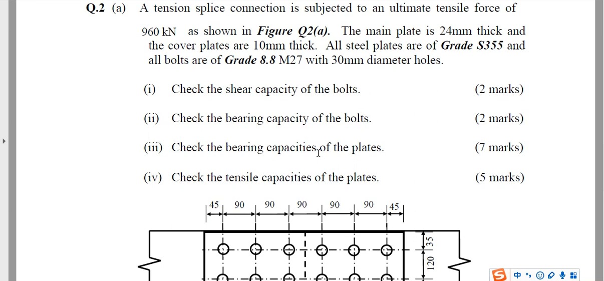
The test has a 24 mm main plate, 10 mm covers, M27 bolts, 30 mm holes and 960 kN ultimate tension. Sketch the three plates in side view and confirm this differs from the earlier 22/12 mm, M24 example.
960 is already factored demand. Do not multiply it by 1.4 or 1.6 again. The four checks trace force from main plate→hole wall→bolt→cover plate, each potentially governed by a different resistance.
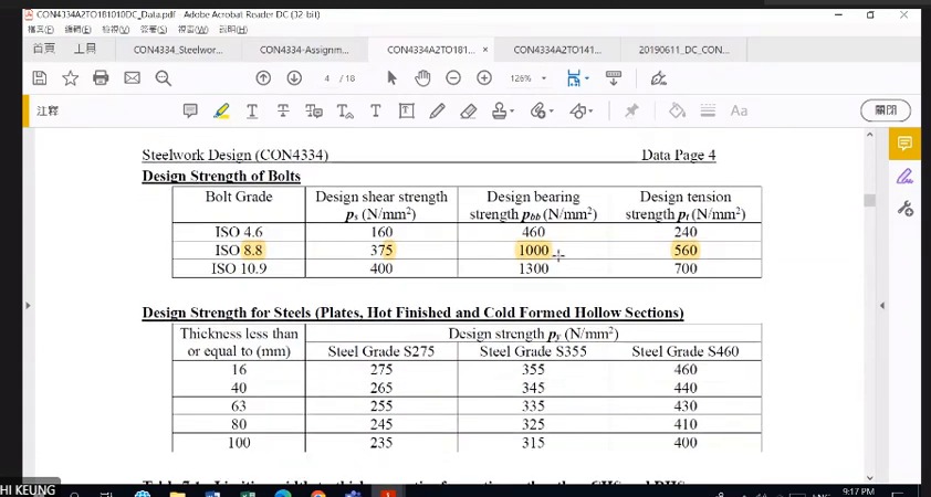
Keep plate and bolt data separate in the tables. Thickness affects plate ; Grade 8.8 has distinct , , and other columns. All are strengths, but they are not interchangeable.
Copy the test conditions correctly first
Main plate thickness is 24 mm; upper and lower covers are 10 mm each. Plates are S355, bolts Grade 8.8 M27 and holes 30 mm. The question requires four capacity checks.
960 kN is already an ultimate tensile force. Do not apply 1.4 or 1.6 again.
Material tables: thickness matters within one steel grade
Grade 8.8 shear, bearing and tension strengths occupy different columns. One value cannot serve every failure mode.
S355 design strength also varies by thickness band. Main and cover plates may require different values for tension resistance .
750 kN replay: double shear and two plates are different factors of 2 (Replay Identity)
What this unit is for: A double-cover splice has two different : each bolt has two shear planes, and there are two cover plates; this unit shows which step each one belongs to.
Picture it this way: Push a chopstick through three stacked pieces of thick card and pull the middle piece out. The chopstick must be cut through at two places before anything comes loose: that is the 2 of double shear. The two outer pieces each take half the force: that is the other 2, used only when checking the cover plates.
Prerequisites: Several failure paths in a bolted connection (Bolted Connections) · How holes weaken a steel plate (Net and Effective Area) · How loads travel from the slab to the ground (Load Path)
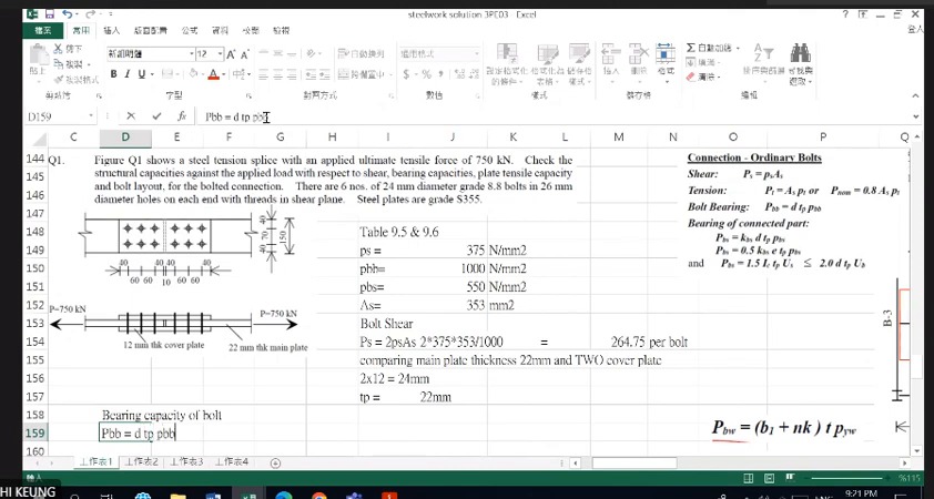
The lecturer replays the old 750 kN worksheet. Six bolts in one half must carry the whole 750 kN; the other half is the next stage of load transfer. Do not average across all twelve.
The double-shear factor 2 comes from two shear planes in one bolt. The cover-bearing factor 2 comes from two plates sharing force in parallel. Calculate each for its own physical object and compare demand with resistance at the same level.
The four bearing bounds cover hole-wall bearing, end distance , clear spacing and the bolt-strength cap. The last uses ; the third uses . Follow the 19 September formulas, list each value and take the minimum.
Complete worked examples in this unit: 750 kN double-cover splice: separate capacity and spacing (Double-cover Splice)
Replayed example: identify it as 750 kN first
This worksheet is for 750 kN with different bolts and plate thicknesses. Draw the axial force path from one main plate, through bolts into two covers, and then to the other main plate.
With six bolts in each half-joint, six must carry the full connection force. Do not divide by all twelve bolts on both sides.
Double shear and bolt bearing are separate checks
With two covers sandwiching the main plate, each bolt normally has two shear planes. Effective area depends on whether the threads cross those planes.
For bolt bearing , consider contact thickness in the central main plate and both covers separately. Two shear planes do not mean every bearing resistance is automatically doubled.
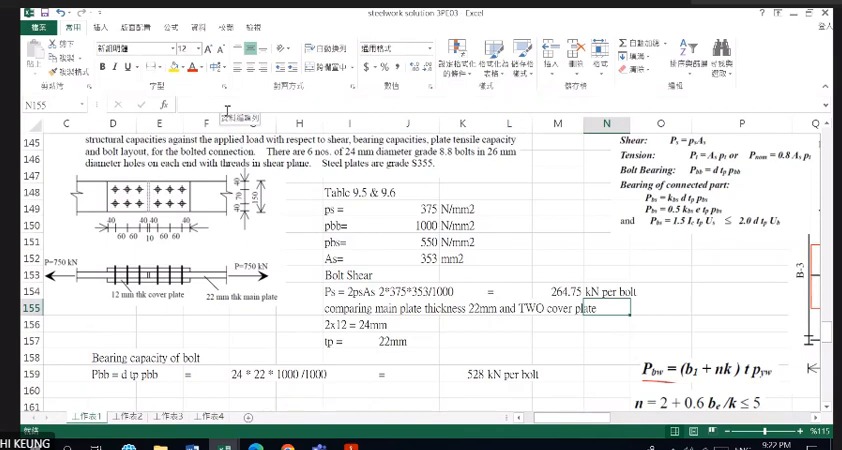
Plate bearing: end distance, hole type and material strength
depends on hole type; is end distance along force transfer, and is the effective clear distance from a hole edge to the plate end or adjacent hole edge.
is plate ultimate tensile strength and bolt ultimate tensile strength. They differ: the course S355 example uses , and Grade 8.8 bolts use .
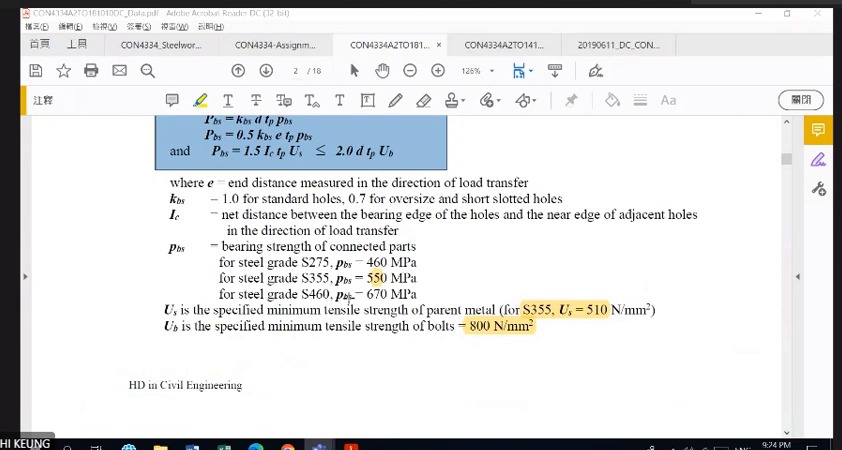
Take the governing bearing value and retain the plate identity
Complete every applicable bearing bound for one plate, take the minimum, then compare with that plate's actual force. List central-plate and cover-plate thicknesses and load shares separately.
Label calculation levels as per bolt, per plate or whole half-joint, avoiding comparisons between different levels of demand and resistance.
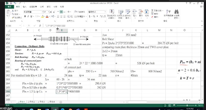
750 kN double-cover splice: separate capacity and spacing (Double-cover Splice)
Two main plates, 150 mm wide and 22 mm thick, are joined end to end by two 12 mm cover plates with 6 M24 bolts at each end. The ultimate pull is 750 kN. Decide whether the bolts, plate bearing and main plate are adequate, and whether the hole spacing meets the rules.
Solution Route: Identify double shear; find governing bolt/plate bearing ; estimate bolt count from resistance; finally check the arrangement.
Return to 960 kN: complete all four calculations (Four Checks)
What this unit is for: The pull passes in turn through the main plate, the hole walls, the bolts and the cover plates; this unit makes four checks along that path and finds the weakest one.
Picture it this way: A chain has several links and the pull must pass through every one, so the weakest link breaks first. A thick main plate does not excuse the cover plates from being checked: the two thin cover plates together are still thinner than the main plate, and in tension they come closest to the limit.
Prerequisites: Several failure paths in a bolted connection (Bolted Connections) · How holes weaken a steel plate (Net and Effective Area) · Material strength and member capacity (Stress and Resistance)
Re-read the test drawing: each half-joint has three columns of two bolts, six total. Width is 35+120+35=190 mm. Longitudinal pitch 90 mm minus hole diameter gives clear spacing 60 mm.
The worked solution follows the taught method, listing expressions, units and comparisons separately for bolt shear, both bearing types and plate tension.
Cover-plate tension is easily missed. A thicker main plate does not necessarily govern. The two 10 mm covers have combined net-section resistance about 1015.3 kN, closer to the 960 kN demand.
Complete worked examples in this unit: 960 kN test question: four checks (Four Checks)
Return to the test: a four-check answer structure
Follow the question order: ① bolt shear; ② bolt bearing ; ③ plate bearing ; ④ plate tension. State capacity, demand and the comparison for each.
Plate bearing and plate tension differ. Bearing concerns local crushing/tearing near holes; tension concerns resistance of the whole net section.
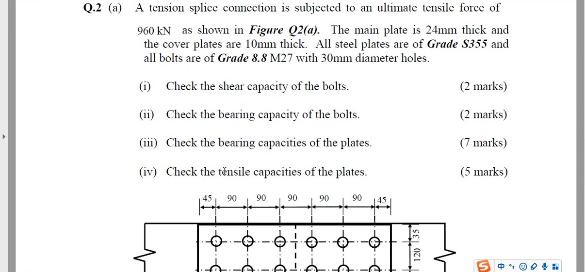
Test drawing: identify the load path and net section
Each half-joint has three columns of two bolts, six total. Longitudinal pitch is 90 mm, end distance , transverse row spacing 120 mm and edge distances 35 mm each.
Plate width is 35+120+35=190 mm. A straight section through two holes deducts 2×30 mm. For the main plate, .
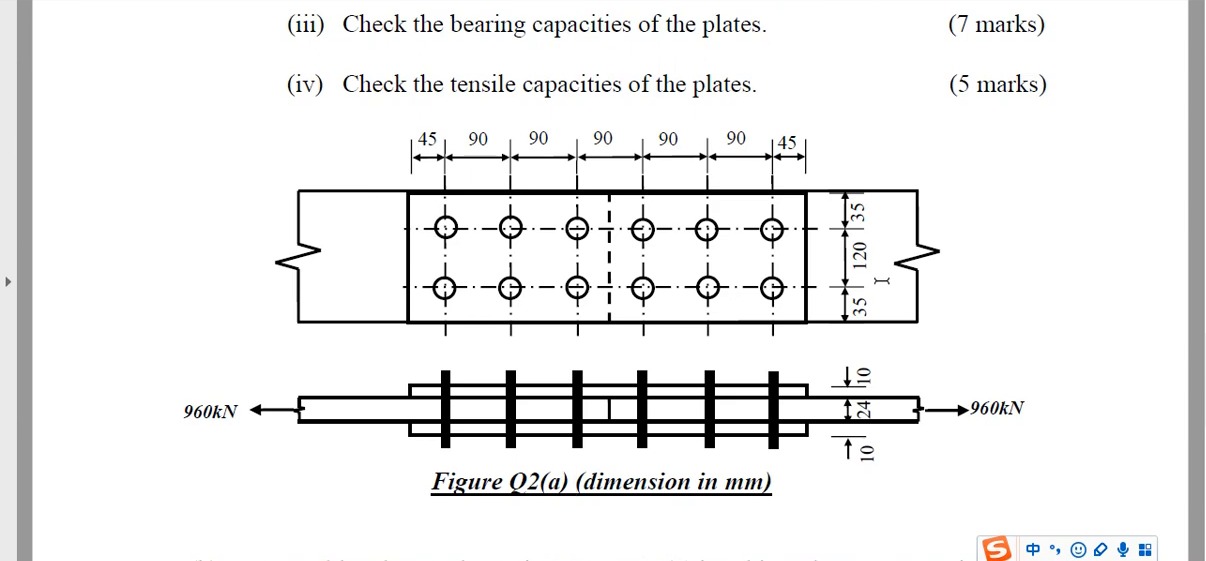
960 kN test question: four checks (Four Checks)
Two 24 mm main plates are joined by two 10 mm cover plates with 6 M27 bolts in each half of the joint. The ultimate pull is 960 kN. Complete four checks: bolt shear, bolt bearing, plate bearing, and tension in the plates.
Solution Route: Half-joint demand→double-shear bolts→bolt bearing →main/cover bearing→net-section tension in both plate types.
Which plate does the replayed 818.2 kN belong to? (Net-section Capacity)
What this unit is for: The tension capacity of a plate depends on its width, hole size and thickness; this unit reworks the main plate of another question and shows why its answer cannot be carried to a different question.
Picture it this way: Plate width minus the width taken by the holes, times thickness, gives the net area. Multiply by , without going above the gross area, to get the effective area. Multiply by to get the tension capacity. adjusts area; it does not increase the load. Change the width, hole size or thickness and all three steps are redone.
Prerequisites: How holes weaken a steel plate (Net and Effective Area) · Material strength and member capacity (Stress and Resistance)
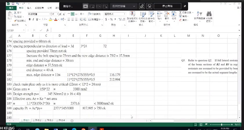
The lecturer returns to tension in the 750 kN example: a 150 mm-wide, 22 mm-thick main plate with two 26 mm holes. These differ from the test, so record 818.2 kN together with its question identity.
Calculate , multiply by and compare with , giving . Only then use for 22 mm thickness to find . adjusts area; do not multiply the load by 1.1.
This is a complete tension example. Compare it with the 960 kN test solution and explain which numbers change because of plate width, hole diameter or thickness, rather than memorising two final answers.
Replay: net area versus effective area
Subtract the diameters of holes crossing the section from plate width, then multiply by thickness for . Apply the course factor and cap the result at gross area .
The course uses for S355. It acts on area; it does not amplify design load by 1.1.
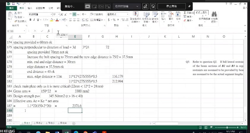
Replay: main-plate tension in the 750 kN example
The replay uses a 150 mm-wide, 22 mm-thick main plate with two 26 mm holes: ; , below .
At that thickness, gives main-plate tension resistance about 818.2 kN, above this example's 750 kN. This completes only main-plate tension, not the other checks.