Tutorial 2 Q6: eccentric welds on two side plates
Open “Animation lab” beside a teaching step for a visual explanation or a walkthrough of its original expressions. Models are illustrative; source answers remain unchanged.
Need a simpler picture? Open “Simple explanation” beside a difficult step. These optional notes do not replace the full solution.
Determine the fillet weld leg for two side plates carrying characteristic dead plus imposed . The load is from the column face. Steel is S355 and electrode Class 42.
Original source: LectureNotes/Ch 2_Connection.pdf — p. 45, p. 48. Values tagged given are in the question or diagram; lookup values come from a named table; calculated values follow from the working; assumptions are stated explicitly.
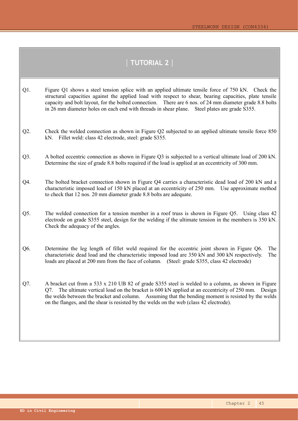
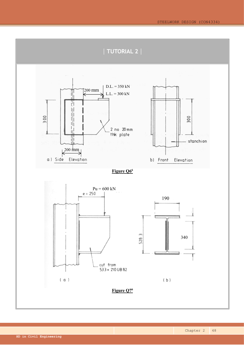
Read the diagram and collect the data
| Quantity | Source and derivation |
|---|---|
| Per-plate load | Two identical side plates in the plan/front arrangement share the total equally. |
| Group size | Use the labelled width and height for each four-sided weld group. |
| Load eccentricity | From group centre to load: half the width plus beyond the face → . |
| Weld model | Uniform all-round fillet represented as a closed line rectangle, as in Connection Example 7. The plate area is not the weld-line area. |
| Size bounds | plate sets minimum under Table 9.1 and edge maximum under . |
Before calculating: recognition and strategy
Two different labels play different roles. One defines the rectangular group width; the other begins at the column face. The centroid is halfway across the group, so the load arm is . Calculate forces per length for one plate using half the load, then select a weld leg that meets resistance and detailing.
1. Factored force, centroid and moment
Equal sharing assumes the displayed symmetric plate pair and centred attachment of the applied load. Using 485 with two weld groups already accounts for both plates; do not double the capacity again within a single group.
Animation labA weld group is a set of lines
Supplement to the original lesson. Enable JavaScript to play, step through calculations and rotate 3D models. The following explanation remains readable offline.
- The centre is empty: resistance comes from the weld lines, not a solid plate filling the group.
- Use line lengths for centroid weighting. Line second moments have units ; add the parallel-axis terms.
- Direct force per length is . The eccentric moment adds tangential flow proportional to distance from the centroid.
- Combine signed components at every candidate corner, then compare the maximum with throat resistance per length.
2. Derive line-weld polar inertia
Simple explanation: Only the weld lines resist as weld
Imagine a wire rectangle: its empty middle is not more wire.
- Count only the weld runs actually shown.
- Use their total length and line second moments.
- Combine direct and torsional forces at the critical location.
Remember: Line second moments have units ; plate-area moments use .
Treat each side as a line. A parallel-axis term is length times distance squared, giving units . This calculation finds force per unit weld length; do not use solid-plate inertia with units .
Animation labA weld group is a set of lines
Supplement to the original lesson. Enable JavaScript to play, step through calculations and rotate 3D models. The following explanation remains readable offline.
- The centre is empty: resistance comes from the weld lines, not a solid plate filling the group.
- Use line lengths for centroid weighting. Line second moments have units ; add the parallel-axis terms.
- Direct force per length is . The eccentric moment adds tangential flow proportional to distance from the centroid.
- Combine signed components at every candidate corner, then compare the maximum with throat resistance per length.
3. Find the critical corner resultant per length
Simple explanation: Add arrows before taking the magnitude
Walking east and walking north do not point in the same direction.
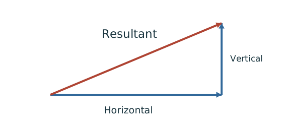
- Choose signed horizontal and vertical directions.
- Add contributions along each direction separately.
- For perpendicular components, use the right-triangle resultant.
Remember: Check the corner where direct and torsional components reinforce each other.
At the opposite edge the vertical components subtract, giving a smaller resultant. Top and bottom corners on the adding side have the same magnitude.
Animation labA weld group is a set of lines
Supplement to the original lesson. Enable JavaScript to play, step through calculations and rotate 3D models. The following explanation remains readable offline.
- The centre is empty: resistance comes from the weld lines, not a solid plate filling the group.
- Use line lengths for centroid weighting. Line second moments have units ; add the parallel-axis terms.
- Direct force per length is . The eccentric moment adds tangential flow proportional to distance from the centroid.
- Combine signed components at every candidate corner, then compare the maximum with throat resistance per length.
4. Select and verify the fillet leg
Simple explanation: Why the weld throat is smaller than its leg
The shortest cut through the weld is thinner than the outside leg.
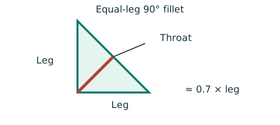
- For the stated equal-leg 90° fillet, throat is approximately 0.7 × leg.
- Multiply throat area by the matching weld design strength.
- For force per length, use a one-millimetre weld strip.
Remember: Choose strength from both the steel grade and electrode class.
The closed all-round group follows the source’s continuous line-weld model; do not treat its four connected sides as four separately terminated / runs without revising the model. Its and sides exceed the minimum effective-length threshold . The selected size completes the requested weld-group resistance under the displayed four-sided, symmetric model. Column local resistance is a separate check not requested or fully specified.
Animation labFrom fillet leg to effective throat
Supplement to the original lesson. Enable JavaScript to play, step through calculations and rotate 3D models. The following explanation remains readable offline.
- An equal-leg fillet between perpendicular plates has an approximately right-triangular section.
- For this geometry, throat . It is shorter than the leg.
- Effective resisting area = . With here, capacity per length is .
- Use the course end allowances, minimum size and length rules; increasing the geometric length alone does not resolve every detailing check.
Compact exam answer
Total ULS load , per plate . Rectangle ,, , . . Direct force , torsional vertical / horizontal ; . ; select an all-around fillet weld on each plate. Resistance , satisfying the size range.
Mistakes to avoid
- The load arm starts at the weld centroid, not the column face.
- Split the force between the two plates once.
- Do not use solid-rectangle inertia.
- Vector-add direct and torsional components at the critical corner.
Procedure for an unfamiliar variant
- Establish the number of parallel weld groups and force per group.
- Locate the weld-line centroid and actual load eccentricity.
- Calculate total line length and polar line inertia.
- Resolve direct/torsional force-per-length components and find their maximum resultant.
- Round weld leg up and verify its capacity and allowed size range.
Independent self-check
Try it yourself. Invented variant: the load is from the group centroid instead of the column face. Find the required leg, keeping other data unchanged.
Reveal answer and reasoning
Torsional vertical component and horizontal component . The strength requirement gives a weld leg of approximately . However, Table 9.1 for a plate still requires at least , so select , resistance , conditional on the same all-around weld model.
Animation labA weld group is a set of lines
Supplement to the original lesson. Enable JavaScript to play, step through calculations and rotate 3D models. The following explanation remains readable offline.
- The centre is empty: resistance comes from the weld lines, not a solid plate filling the group.
- Use line lengths for centroid weighting. Line second moments have units ; add the parallel-axis terms.
- Direct force per length is . The eccentric moment adds tangential flow proportional to distance from the centroid.
- Combine signed components at every candidate corner, then compare the maximum with throat resistance per length.