Tutorial 2 Q3: size bolts for an in-plane eccentric pair of plates
Open “Animation lab” beside a teaching step for a visual explanation or a walkthrough of its original expressions. Models are illustrative; source answers remain unchanged.
Need a simpler picture? Open “Simple explanation” beside a difficult step. These optional notes do not replace the full solution.
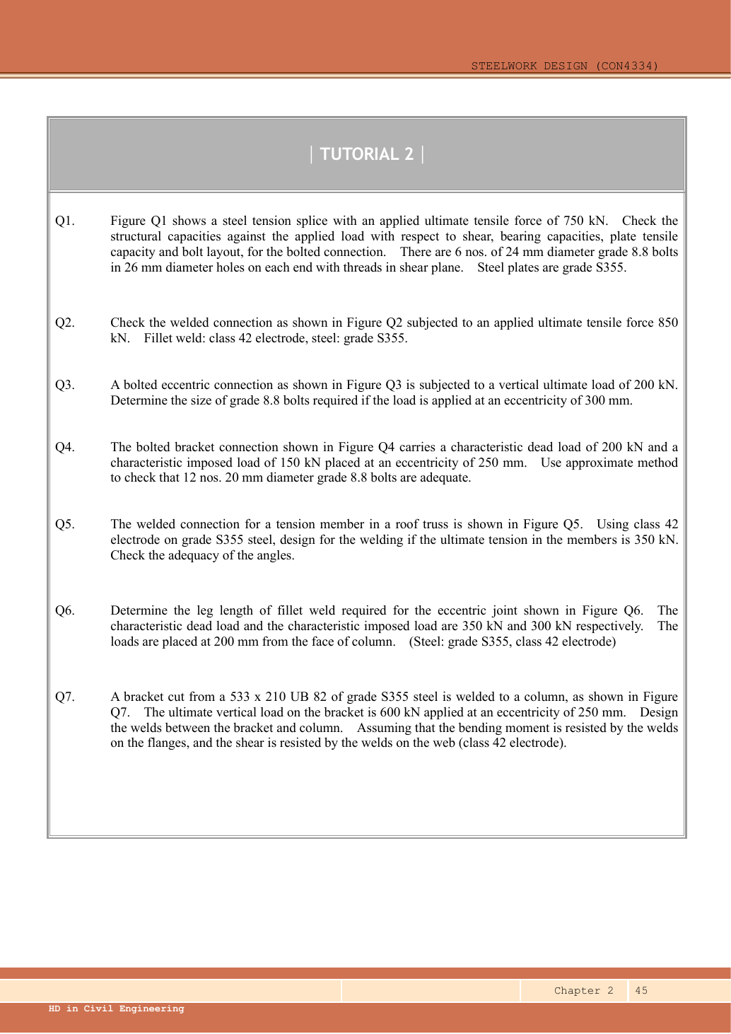
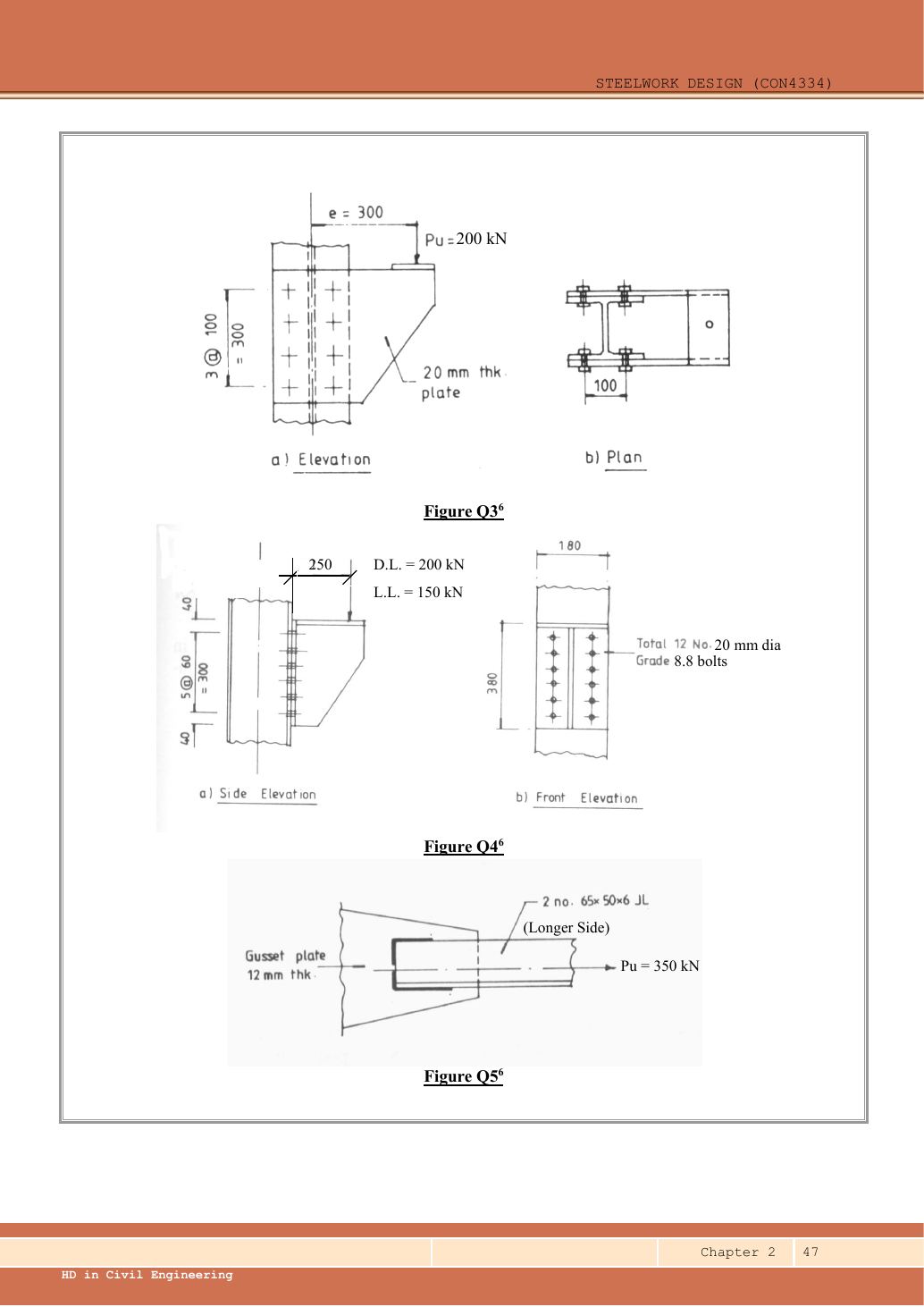
Determine the Grade 8.8 bolt size for the eccentric connection carrying ultimate vertical load at eccentricity . The drawing shows two side plates.
Original source: LectureNotes/Ch 2_Connection.pdf — p. 45, p. 47. Values tagged given are in the question or diagram; lookup values come from a named table; calculated values follow from the working; assumptions are stated explicitly.
Read the diagram and collect the data
| Quantity | Interpretation |
|---|---|
| Symmetric pair | The plan shows a side plate on each side; assume symmetric load sharing between identical plates. Each plate takes . |
| Per-plate bolt pattern | Eight bolts: ; about its centroid. |
| Shear planes | Each bolt joins a side plate to its column flange; use single-shear capacity for that plate load. |
| Threads | Not specified; conservatively use tensile stress area, as if threads cross the plane. |
| Missing dimensions | Column-flange thickness and bolt edge distances are not supplied; bolt-size shear solution does not certify those bearing/detailing checks. |
Before calculating: recognition and strategy
This is torsion in the plate plane, unlike the bolt-tension bracket in Q4. Split the total load between the two geometrically identical side plates. For one plate combine uniform direct shear with the tangential force from . The bolt farthest from the centroid is a candidate, but use components and choose the side where vertical components add.
1. Coordinates and group polar sum
Simple explanation: An off-centre force also tries to turn the group
Pulling away from the centre causes a push plus a twist.
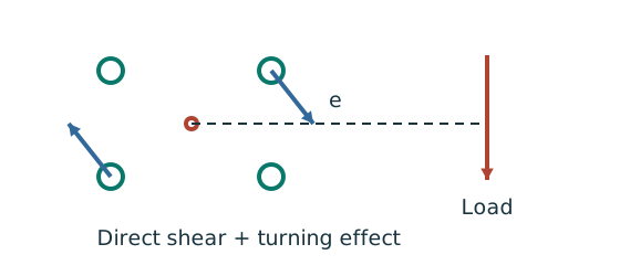
- Find direct shear and moment about the bolt-group centroid.
- Moment-induced forces act tangentially; farther bolts attract more.
- Add horizontal and vertical components before finding the resultant.
Remember: Do not simply add two force magnitudes pointing in different directions.
This is a sum of bolt radius-squared values, with units. Do not use a weld-line polar inertia, which has units.
Animation labAdd direct and torsional bolt forces
Supplement to the original lesson. Enable JavaScript to play, step through calculations and rotate 3D models. The following explanation remains readable offline.
- Assign signed coordinates to the bolts relative to the group centroid.
- For the equal-bolt elastic model, the direct force is per bolt.
- Moment magnitude is ; its sign follows the load direction. For signed M: , , .
- Add signed x and y components at each bolt, then take the resultant. The longest arrow shows the critical bolt in this illustration.
2. Resolve direct and torsional forces
Simple explanation: Add arrows before taking the magnitude
Walking east and walking north do not point in the same direction.
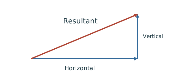
- Choose signed horizontal and vertical directions.
- Add contributions along each direction separately.
- For perpendicular components, use the right-triangle resultant.
Remember: Check the corner where direct and torsional components reinforce each other.
At the opposite bolt column the vertical components subtract to zero, so its corner resultant is . Interior rows have smaller horizontal torsional components. Thus is the maximum.
Animation labAdd direct and torsional bolt forces
Supplement to the original lesson. Enable JavaScript to play, step through calculations and rotate 3D models. The following explanation remains readable offline.
- Assign signed coordinates to the bolts relative to the group centroid.
- For the equal-bolt elastic model, the direct force is per bolt.
- Moment magnitude is ; its sign follows the load direction. For signed M: , , .
- Add signed x and y components at each bolt, then take the resultant. The longest arrow shows the critical bolt in this illustration.
3. Select a bolt size using the supplied table
This means eight bolts per plate and sixteen in the symmetric pair. For standard holes M16 would use holes under the course rule. The question does not give the column-flange thickness or end/edge dimensions, so verify bearing and detailing when those are supplied. If the were intended to act on one plate alone, the resultant would double to , requiring at least M20 by shear. The displayed plan supports the symmetric two-plate model used here; this alternative shows why load-sharing assumptions must be stated.
Animation labCount the bolt shear planes
Supplement to the original lesson. Enable JavaScript to play, step through calculations and rotate 3D models. The following explanation remains readable offline.
- Load must cross an interface between the connected plates.
- A lap joint gives one shear plane through a bolt.
- A symmetric double-cover joint may provide two shear planes. Count load-transfer interfaces, not just visible plates.
- Use the source’s area and shear strength. Then check bearing, plate resistance and detailing separately.
Compact exam answer
Symmetric two-plate model: . Eight bolts per plate, ,; . ; moment produces corner vertical component and horizontal component . . ; Grade 8.8 M16 single-shear resistance , passes. Bearing/detailing checks still require the missing flange and edge-distance information.
Mistakes to avoid
- Do not halve the load twice.
- Do not read as the group’s half-height.
- Do not add horizontal and vertical forces arithmetically.
- Do not call the chosen bolt a fully checked connection without bearing inputs.
Procedure for an unfamiliar variant
- Identify the force path and whether the joint is concentric, in-plane eccentric or out-of-plane eccentric.
- Read all dimensions from the relevant view; do not measure drawing scale.
- Distinguish characteristic from ultimate loads and factor only when needed.
- Calculate demand per fastener/weld with the appropriate equilibrium model.
- Check all requested resistances and detailing conditions separately.
- State whether the given detail passes, fails, or remains conditional on missing data.
Independent self-check
Try it yourself. Invented variant: total load remains but eccentricity becomes . Does M16 still pass the same shear model?
Reveal answer and reasoning
Per plate . Torsional vertical component and horizontal component ; direct vertical shear . Resultant: Passes by only a small margin. All bearing/detailing conditions still require their respective data.
Animation labAdd direct and torsional bolt forces
Supplement to the original lesson. Enable JavaScript to play, step through calculations and rotate 3D models. The following explanation remains readable offline.
- Assign signed coordinates to the bolts relative to the group centroid.
- For the equal-bolt elastic model, the direct force is per bolt.
- Moment magnitude is ; its sign follows the load direction. For signed M: , , .
- Add signed x and y components at each bolt, then take the resultant. The longest arrow shows the critical bolt in this illustration.