Note: marks are as printed in the paper; the working is a teaching guide, not an official marking scheme.
Separate vertical supports from lateral restraints
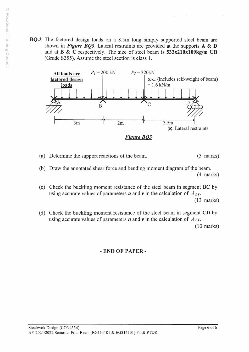
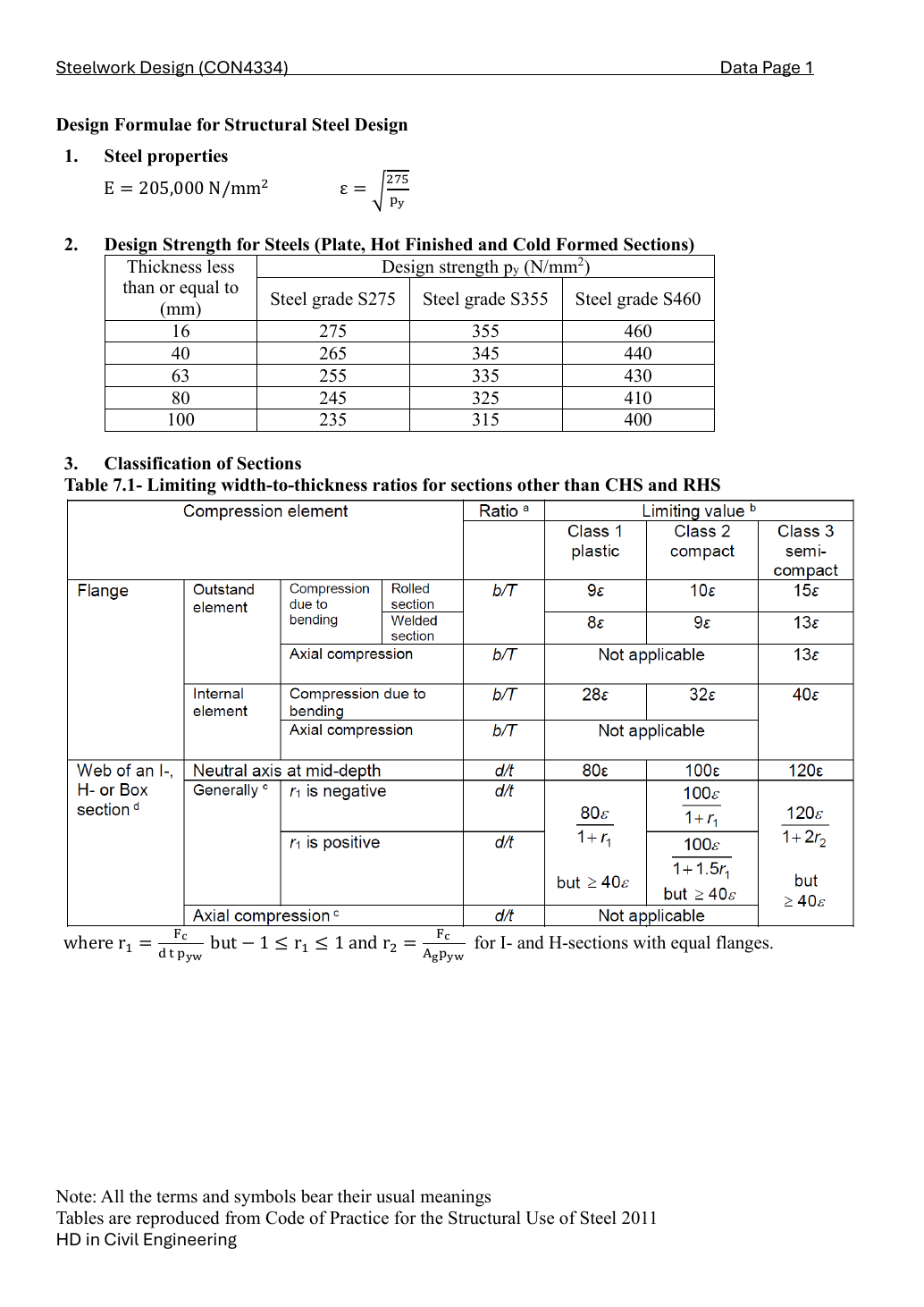
Given: A and D are the simple vertical supports, 8.5 m apart. B is 3 m from A, C another 2 m to the right, and D another 3.5 m. Downward factored point loads are 200 kN at B and 320 kN at C. The full-length factored UDL is 1.6 kN/m including self-weight. Lateral restraints occur at A, B, C and D; they split the buckling lengths but do not create extra vertical reactions. Section 533 × 210 × 109 UB is S355, Class 1.
Simple explanation — open only if needed
A hand stopping a ruler moving sideways is not the same as a prop holding its weight up. Solve vertical reactions using the actual props first; use the side restraints only when deciding which length can twist sideways.
BQ3(a) — support reactions [3 marks]
Take moments about A to eliminate its reaction. The UDL resultant is its intensity times the full span and acts at the span centre. Then use vertical force equilibrium.
W=1.6(8.5)=13.6kN,xW=8.5/2=4.25m
RD=8.5200(3)+320(5)+13.6(4.25)=265.623529kN
RA=200+320+13.6−RD=267.976471kN
Both reactions are upward; together they equal 533.6 kN. Already factored loads receive no second load factor.
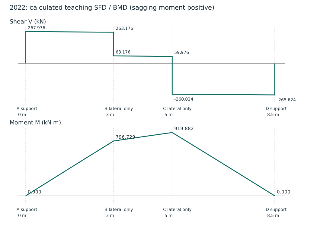
BQ3(b) — annotated shear and moment diagrams [4 marks]
Use x in metres measured from A, positive sagging moment, and shear equal to the sum of vertical forces to the left. At a downward point load, shear jumps down but moment stays continuous. Between loads, the UDL makes shear linear and moment quadratic.
V(x)=267.976471−1.6x−200H(x−3)−320H(x−5)[kN]
M(x)=267.976471x−0.8x2−200⟨x−3⟩−320⟨x−5⟩[kNm]
H is zero before its load and one after; the angle-bracket term means use zero before the load and the positive distance after it. This is only a compact way to write the ordinary left-of-section force and moment sums.
Position
Shear just left → right (kN)
Moment (kN·m)
A
0 → 267.976471
0
B
263.176471 → 63.176471
796.729412
C
59.976471 → -260.023529
919.882353
D
-265.623529 → 0
0
MB=267.976471(3)−0.8(32)=796.729412kNm
MC=267.976471(5)−0.8(52)−200(5−3)=919.882353kNm
Shear is positive up to C and negative after C, so C is the maximum sagging moment. The computed end moment at D is zero, checking the reaction arithmetic.
Calculated teaching diagrams: all jumps, supports and moment ordinates are labelled; curves include the UDL. Full-size image
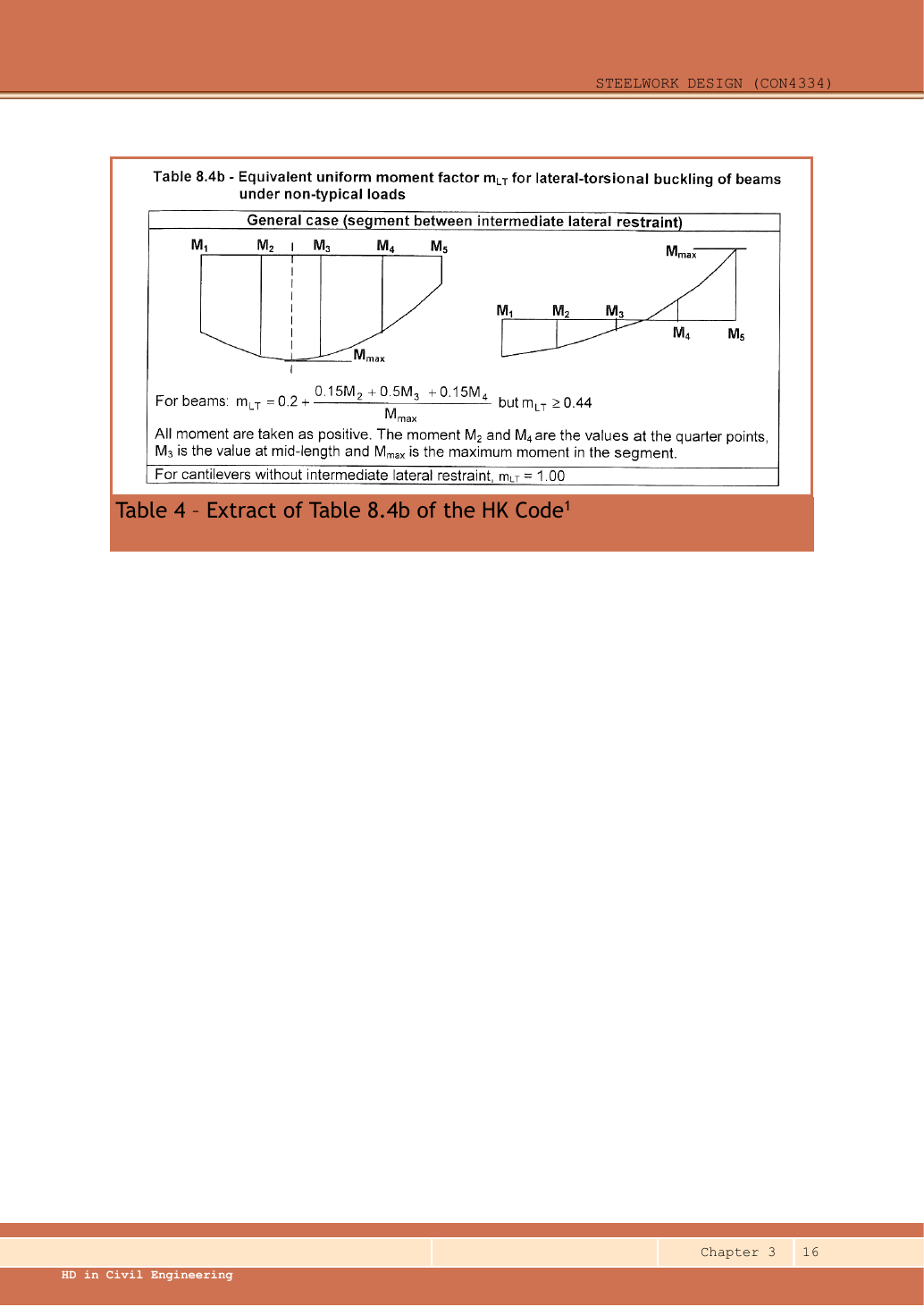
Use the moments at one-quarter, one-half and three-quarters of THIS restrained segment. They are not necessarily at load points. Evaluate the actual quadratic bending diagram including the UDL; use absolute magnitudes in the quarter-point expression and compare with the maximum absolute moment in the segment.
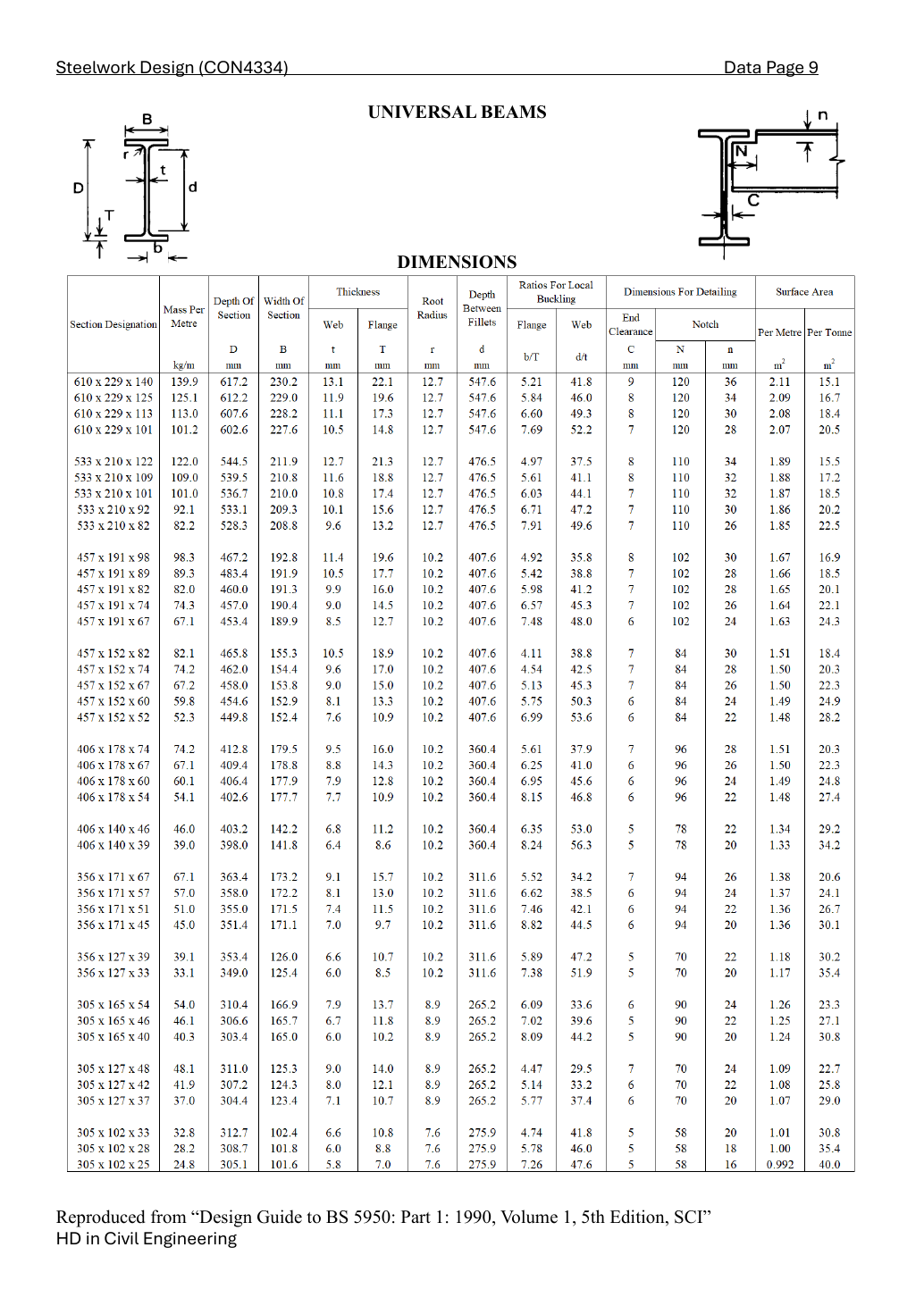
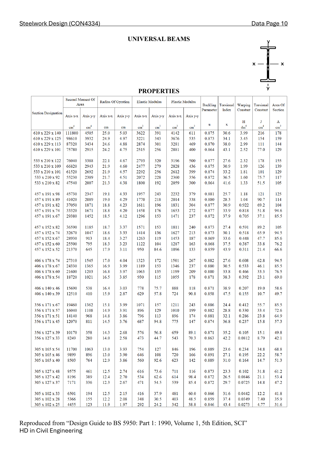
Use millimetres in slenderness. The section table supplies the minor-axis radius of gyration, buckling parameter and torsional index; the given Class 1 section has a plastic-section factor of one. These quantities change when the section changes.
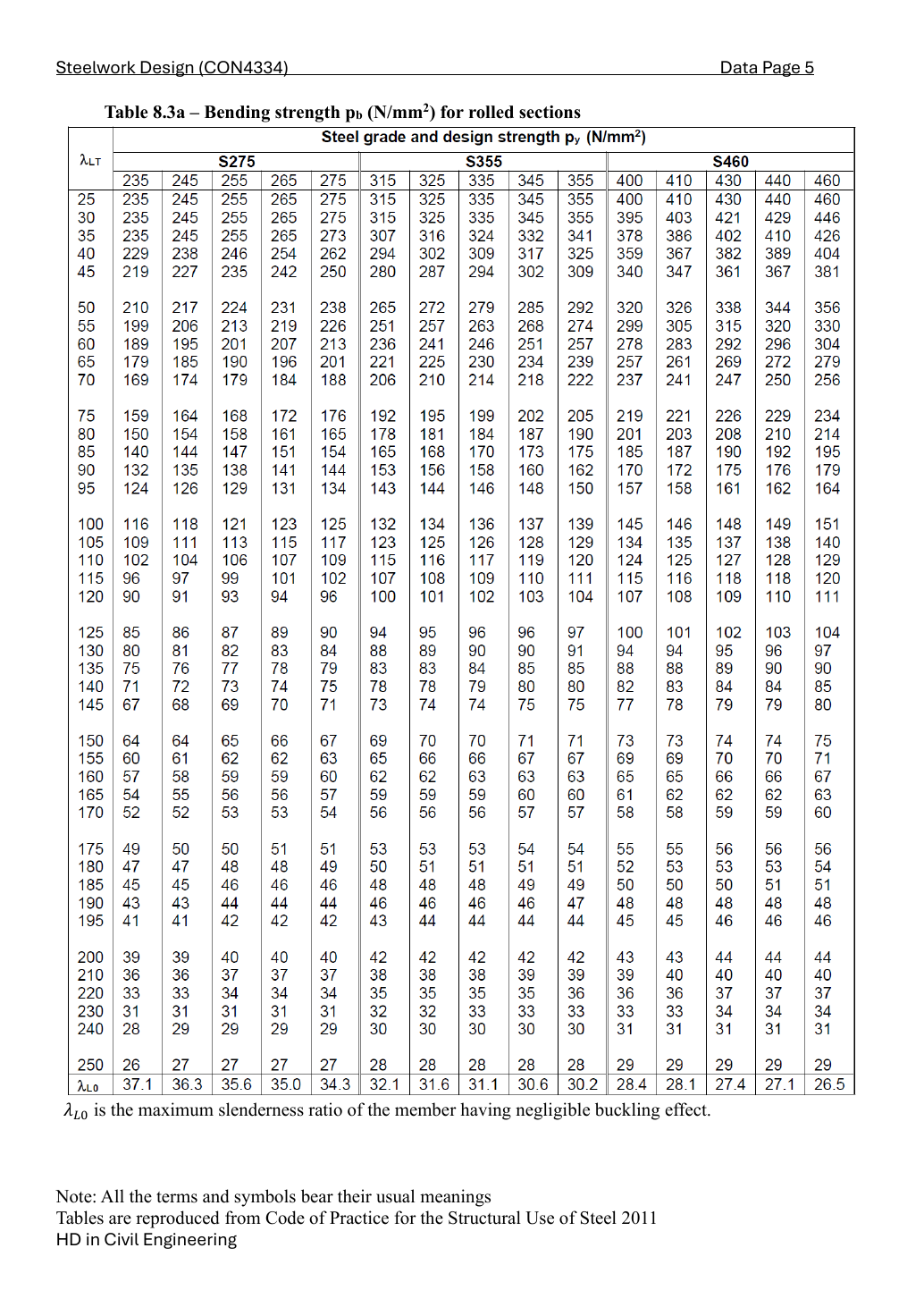
Choose Data File p.5, Table 8.3, 345 N/mm² column. Interpolate between the two surrounding slenderness rows in the same design-strength column; do not mix columns.
Buckling strength times plastic modulus gives moment resistance. Convert the tabulated cubic centimetres to cubic millimetres, then newton-millimetres to kilonewton-metres.
Use the moments at one-quarter, one-half and three-quarters of THIS restrained segment. They are not necessarily at load points. Evaluate the actual quadratic bending diagram including the UDL; use absolute magnitudes in the quarter-point expression and compare with the maximum absolute moment in the segment.
Use millimetres in slenderness. The section table supplies the minor-axis radius of gyration, buckling parameter and torsional index; the given Class 1 section has a plastic-section factor of one. These quantities change when the section changes.
Choose Data File p.5, Table 8.3, 345 N/mm² column. Interpolate between the two surrounding slenderness rows in the same design-strength column; do not mix columns.
Buckling strength times plastic modulus gives moment resistance. Convert the tabulated cubic centimetres to cubic millimetres, then newton-millimetres to kilonewton-metres.
Both segments pass the stated normal-loading/effective-length branch; provide SFD/BMD and restraint qualification.
Common mistakes
B and C lateral restraints are not extra vertical supports.
Quarter points belong to each segment, not the entire 8.5 m beam.
Do not replace the curved CD moment diagram with an exact straight triangle.
Procedure for a new variant
Find vertical reactions and the full SFD/BMD.
Identify actual restraints and effective lengths.
Evaluate segment quarter moments, mLT, slenderness and table strength.
Independent self-check — invented variant
Invented variant: add a lateral restraint halfway through CD without changing vertical supports. Do reactions change?
Hint
Separate vertical statics from lateral buckling.
Answer and reasoning
No. Vertical reactions and the existing bending diagram stay the same. Split CD into two LTB segments, choose the new effective lengths and recompute each segment’s quarter-point factor and resistance.