Mock Q1: full solution and invented marking guide
Open “Animation lab” beside a teaching step for a visual explanation or a walkthrough of its original expressions. Models are illustrative; source answers remain unchanged.
Need a simpler picture? Open “Simple explanation” beside a difficult step. These optional notes do not replace the full solution.
Open only after attempting the question. Return to question. All marking guidance here is invented.
(a) Load intensity
Simple explanation: Why dead and imposed loads stay separate
Keep two shopping baskets until their different multipliers are applied.
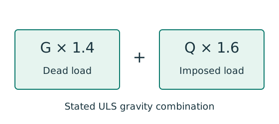
- Put self-weight and permanent finishes in the dead-load basket.
- Put the specified use load in the imposed-load basket.
- For this course’s stated gravity combination: .
Remember: That ULS combination is not the imposed-load deflection load.
Animation labFrom characteristic to design load
Supplement to the original lesson. Enable JavaScript to play, step through calculations and rotate 3D models. The following explanation remains readable offline.
- G is permanent load; Q is imposed load. A surface load and a line load also have different units.
- This illustration uses the course gravity case . Other combinations in the original text retain their own factors.
- For illustrative , change Q and watch each separate contribution.
- Do not carry this ULS total automatically into deflection. Follow the stated SLS load case.
(b) Trace the load path and calculate actions
Simple explanation: How a floor load reaches a beam
Each beam collects the load from its own strip of floor.
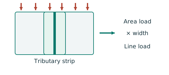
- Find the tributary width from the actual plan.
- Area load × tributary width gives load per beam length.
- A supporting beam receives the other beam’s end reaction.
Remember: A reaction becomes a point load, not automatically a UDL.
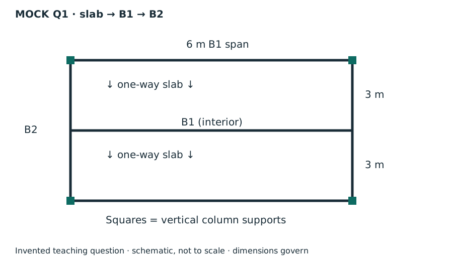
Interior B1 collects half of each slab bay:. The B2 midpoint receives one B1 end reaction; top/bottom edge B1 reactions arrive directly at columns. Those edge reactions do not add midpoint bending to B2.
Animation labFollow the floor load in 3D
Supplement to the original lesson. Enable JavaScript to play, step through calculations and rotate 3D models. The following explanation remains readable offline.
- The floor carries pressure in . The highlighted strip belongs to one secondary beam.
- Multiply pressure by tributary width: . The illustration uses .
- A primary beam receives the secondary beam reaction at their connection, not a new full-span UDL.
- Trace reactions down to columns and foundations. Count each loaded area once.
(c) Read exact rows and classify
Simple explanation: A thin part can wrinkle first
A thin plate may wrinkle before the whole steel member reaches its intended resistance.
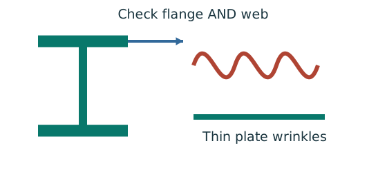
- Check flange and web slenderness using their own definitions.
- Compare each ratio with the correct class limits.
- The less favourable element determines the section class.
Remember: Bending limits and uniform-compression limits are different.
Lookup: Data File pp.9–10, exact UB row. Dimensions on p.9; properties on p.10. is overall depth; is the clear web depth between root fillets, not the nominal designation.
| Property | Lookup value / conversion |
|---|---|
| Dimensions | D454.6, web t 8.1, flange T13.3, root r 10.2, clear d 407.6, all |
| Local ratios | ;。 |
| Major-axis properties | ; ; . |
| LTB properties | ; ; torsional index . |
Lookup: Data File pp.9–10, exact UB row. Dimensions on p.9; properties on p.10. is overall depth; is the clear web depth between root fillets, not the nominal designation.
| Property | Lookup value / conversion |
|---|---|
| Dimensions | D533.1, web t 10.1, flange T15.6, root r 12.7, clear d 476.5, all |
| Local ratios | ;。 |
| Major-axis properties | ; ; . |
| LTB properties | ; ; torsional index . |
Animation labWhy thin elements buckle locally
Supplement to the original lesson. Enable JavaScript to play, step through calculations and rotate 3D models. The following explanation remains readable offline.
- The flange outstand and web have different widths, thicknesses and edge support conditions.
- A thinner plate can wrinkle locally before the complete member loses stability.
- Class 1 allows plastic rotation; Class 2 reaches plastic resistance; Class 3 reaches elastic resistance; Class 4 requires effective properties.
- Check every relevant compression element with the supplied limits and stress distribution. The deformation shown is qualitative.
(d) B1 resistance and deflection
Simple explanation: How much does the beam sag?
Strength asks whether it fails; deflection asks how far it moves.
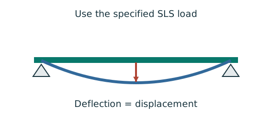
- Use the serviceability load case specified by the course question.
- Choose the expression matching the support and load positions.
- Use consistent units for load, length, E and I.
Remember: The largest deflection is not always at midspan.
Animation labSee shear in the web
Supplement to the original lesson. Enable JavaScript to play, step through calculations and rotate 3D models. The following explanation remains readable offline.
- Internal shear keeps the two sides of the cut in vertical equilibrium.
- For the course’s common I-section case, the web provides the principal shear area; use the specified definition.
- A slender web may require a different shear-buckling route before a simple shear-resistance formula is used.
- Use where applicable in the course. Convert N to kN before comparing with design shear.
(e) B2 resistance and deflection
Full lateral restraint is explicitly supplied, so no LTB check is needed here. This does not establish an unspecified web-contact detail; the mock expressly excludes that scope.
Animation labSee shear in the web
Supplement to the original lesson. Enable JavaScript to play, step through calculations and rotate 3D models. The following explanation remains readable offline.
- Internal shear keeps the two sides of the cut in vertical equilibrium.
- For the course’s common I-section case, the web provides the principal shear area; use the specified definition.
- A slender web may require a different shear-buckling route before a simple shear-resistance formula is used.
- Use where applicable in the course. Convert N to kN before comparing with design shear.
(f) Strength versus stiffness
Simple explanation: Strong enough and stiff enough are two questions
A shelf can avoid breaking yet still sag too much.
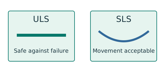
- ULS checks safety against the relevant failure modes.
- SLS checks the specified everyday-use limit.
- Use the load case required for each check.
Remember: Passing bending resistance does not prove deflection passes.
Strength concerns resistance to yielding/failure, using design strength and capacities. Stiffness concerns elastic deformation, usingE andI. A higher grade can raise bending resistance without changing the courseE; changing section depth can substantially increaseI and reduce deflection. Therefore a member may pass strength and fail serviceability.
Animation labSee stiffness and deflection
Supplement to the original lesson. Enable JavaScript to play, step through calculations and rotate 3D models. The following explanation remains readable offline.
- Use the specified SLS load, span and support arrangement. The demonstrator has a full-span UDL.
- The loaded beam bends; the deformation is exaggerated so its shape can be seen.
- For a simply supported full-span UDL, . Double L with w, E and I unchanged: δ becomes 16 times as large.
- The readout uses , and . Select the finish/support-specific limit from the original table.
Compact script and invented marking guide
| Part | Results / suggested credit |
|---|---|
| a /4 | , ; correct thickness units, each worth marks. |
| b /8 | B1 w 34.2212,V102.664,M153.995; B2 P102.664,w 1.2894,V55.,M159.798. Credit load path , line loads , reactions , moments . |
| c /4 | BothClass 1; per correctly justified section. |
| d /10 | Shear , low-shear/bending , service load , deflection/limit . . |
| e /10 | Same distribution. ; use imposed reaction only. |
| f /4 | per explained distinction, including one implication. |
Animation labFollow the calculation sequence
Supplement to the original lesson. Enable JavaScript to play, step through calculations and rotate 3D models. The following explanation remains readable offline.
- Locate the load, supports, connection geometry and any stated assumptions.
- Keep given values, table lookups and calculated values distinct; reconcile their units.
- The calculation player steps through the existing expressions in their original order.
- Compare demand with resistance or the relevant limit. Keep missing inputs and conditional conclusions explicit.