2024 BQ2(b): four-sided weld on a channel web
Open “Animation lab” beside a teaching step for a visual explanation or a walkthrough of its original expressions. Models are illustrative; source answers remain unchanged.
Need a simpler picture? Open “Simple explanation” beside a difficult step. These optional notes do not replace the full solution.
Determine the required fillet-weld leg for the S355 plate welded on four sides to a parallel-flange-channel web, using Class 42 electrode. Rectangle wide by high. Characteristic dead and imposed act on the right edge line.
Original source: Pastpaper/23ENGTY004.pdf — p. 4. Values tagged given are in the question or diagram; lookup values come from a named table; calculated values follow from the working; assumptions are stated explicitly.
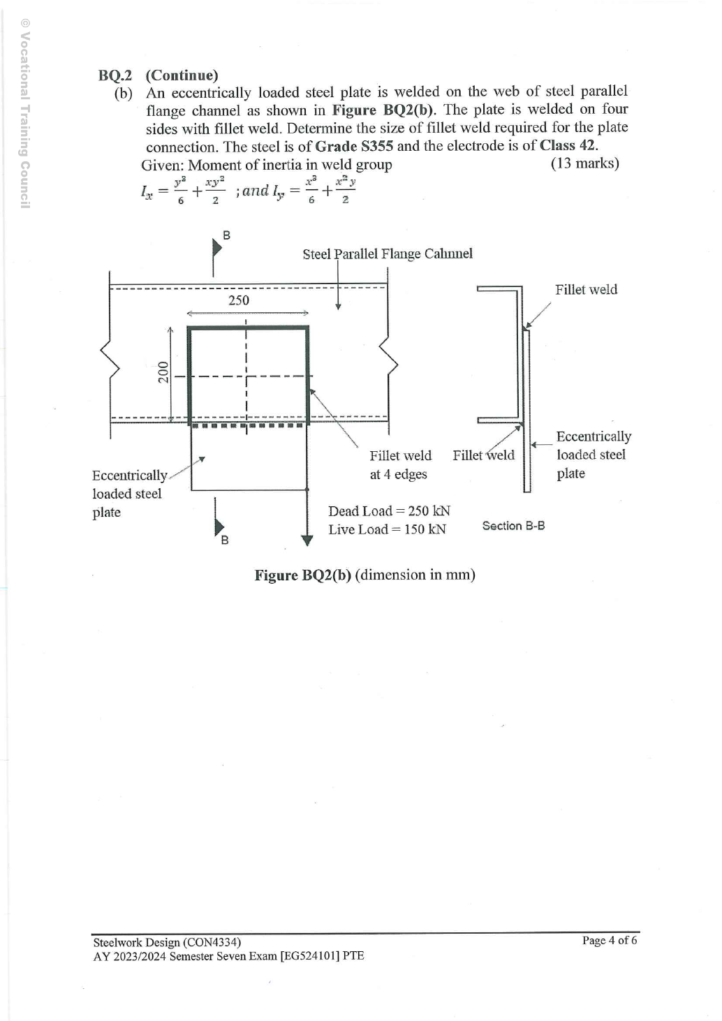
Read the diagram and collect the data
| Input | Origin |
|---|---|
| Loads | Given dead and live ; apply the course ULS combination once. |
| Geometry | GivenB250,H200 mm; symmetry gives corner coordinates/. |
| Given formulas | The formula on the complete original exam page is and ; in that source expression, , denote full rectangle width and height respectively. The website working uses , to avoid confusion with corner coordinates, writing and . These are weld-line inertias, in ; the two notations are equivalent after matching their definitions. |
| Weld strength | S355/Class 42 gives ; equal-leg weld throat . |
| Absent detail | Plate and channel-web thicknesses are not given; exposed-edge maximum leg requires their actual values. |
Before calculating: recognition and strategy
Separate the direct vertical line force from the moment-induced tangential force. The critical corner is the side where the torsional vertical component adds to direct shear. Use the given line-inertia formulas with full rectangle dimensions, then resolve components before selecting a weld leg.
Complete 13-mark solution: load, line inertia, corner resultant and size
Simple explanation: Only the weld lines resist as weld
Imagine a wire rectangle: its empty middle is not more wire.
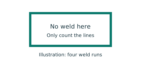
- Count only the weld runs actually shown.
- Use their total length and line second moments.
- Combine direct and torsional forces at the critical location.
Remember: Line second moments have units ; plate-area moments use .
Simple explanation: Add arrows before taking the magnitude
Walking east and walking north do not point in the same direction.
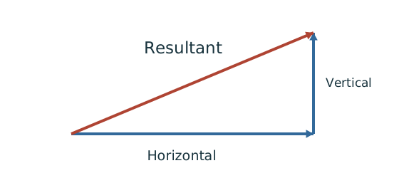
- Choose signed horizontal and vertical directions.
- Add contributions along each direction separately.
- For perpendicular components, use the right-triangle resultant.
Remember: Check the corner where direct and torsional components reinforce each other.
Simple explanation: Why the weld throat is smaller than its leg
The shortest cut through the weld is thinner than the outside leg.
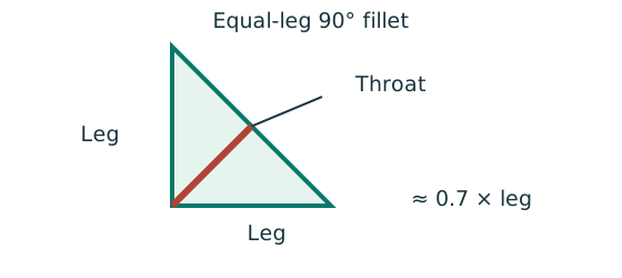
- For the stated equal-leg 90° fillet, throat is approximately 0.7 × leg.
- Multiply throat area by the matching weld design strength.
- For force per length, use a one-millimetre weld strip.
Remember: Choose strength from both the steel grade and electrode class.
For the continuous closed-perimeter course model, use the rectangle’s full effective line. Separate terminated runs would require their actual end deductions and revised geometry; the question’s provided inertia formulas assume this continuous rectangle.
Both stresses are now expressed as force per effective weld length, so vector combination is dimensionally valid. The opposite side subtracts the torsional vertical component and does not govern.
meets every minimum-leg value listed in the source table, whose largest minimum is . However the thinner exposed edge must allow that leg: under the source rule, requires . Neither thickness is supplied, so that maximum-size applicability remains unverified.
Animation labA weld group is a set of lines
Supplement to the original lesson. Enable JavaScript to play, step through calculations and rotate 3D models. The following explanation remains readable offline.
- The centre is empty: resistance comes from the weld lines, not a solid plate filling the group.
- Use line lengths for centroid weighting. Line second moments have units ; add the parallel-axis terms.
- Direct force per length is . The eccentric moment adds tangential flow proportional to distance from the centroid.
- Combine signed components at every candidate corner, then compare the maximum with throat resistance per length.
Compact exam answer
, , , . , , . Governing , , resultant . ; trial for strength ,. Maximum weld leg at the edge depends on unprovided thickness information, so fabrication details cannot be confirmed unconditionally.
Mistakes to avoid
- Do not use as the centroid eccentricity.
- Do not halve : there is one loaded group.
- Use line inertia, not plate-area inertia.
- Do not ignore the maximum permitted edge weld size.
Procedure for an unfamiliar variant
- Locate the load line relative to the weld centroid.
- Factor characteristic loads and computePe.
- Compute line length and both line inertias.
- Resolve the corner torsional components and add direct shear with signs.
- Convert resultant to leg and check the actual detail limits.
Independent self-check
Try it yourself. Invented variant: both characteristic loads increase proportionally. Does the strength trial pass?
Reveal answer and reasoning
The resultant increases to , above . The trial fails strength even though the original utilisation was below . Geometry/materials unchanged means resistance does not scale with load.
Animation labA weld group is a set of lines
Supplement to the original lesson. Enable JavaScript to play, step through calculations and rotate 3D models. The following explanation remains readable offline.
- The centre is empty: resistance comes from the weld lines, not a solid plate filling the group.
- Use line lengths for centroid weighting. Line second moments have units ; add the parallel-axis terms.
- Direct force per length is . The eccentric moment adds tangential flow proportional to distance from the centroid.
- Combine signed components at every candidate corner, then compare the maximum with throat resistance per length.