Column example 4: tributary area and cumulative column loads
Open “Animation lab” beside a teaching step for a visual explanation or a walkthrough of its original expressions. Models are illustrative; source answers remain unchanged.
← Read this lecture example beside its chapter concepts
Need a simpler picture? Open “Simple explanation” beside a difficult step. These optional notes do not replace the full solution.
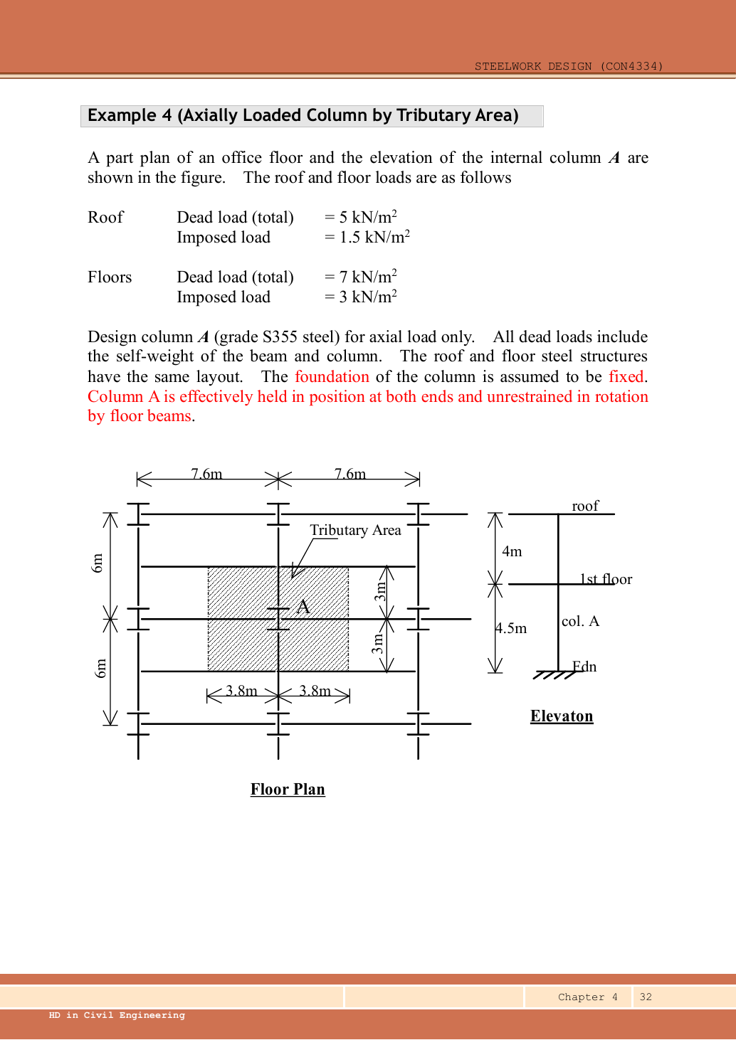
Design internal column A in S355 for axial load only. Roof dead/imposed intensities are /; floor intensities /. Upper storey height ; lower . The foundation is fixed. Floor beams prevent translation but do not restrain column rotation. All given dead loads include beam and column self-weight.
Original source: LectureNotes/Ch 4_Column.pdf — p. 32, p. 33, p. 34, p. 35. Values tagged given are in the question or diagram; lookup values come from a named table; calculated values follow from the working; assumptions are stated explicitly.
Read the diagram and collect the data
| Input | Where to read it |
|---|---|
| Tributary dimensions | Plan labels and ; use plan area, not storey height. |
| Vertical dimensions | Elevation upper and lower. |
| Roof/floor loads | Question text; the same floor plan applies at both levels. |
| Axial-only scope | Explicitly requested; no eccentric moment is introduced into this exercise. |
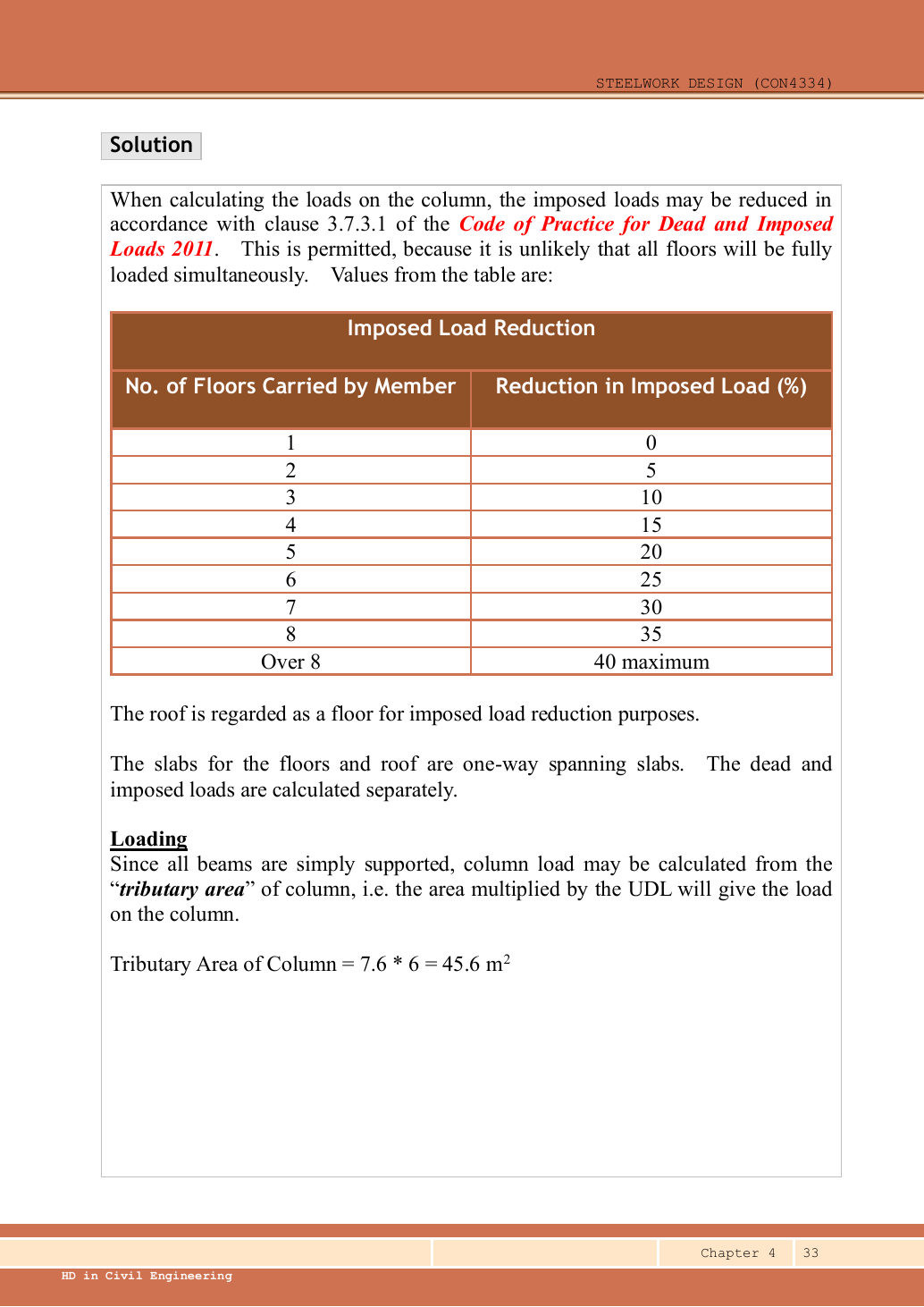
| Imposed reduction | Lecture p.33 applies its 2011 load-code floor-count table; roof counts as a floor. |
Before calculating: recognition and strategy
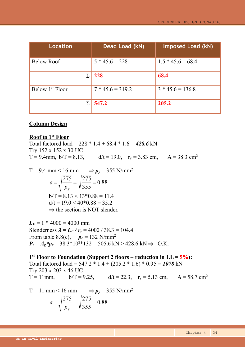
Multiply each level’s pressure by the area feeding the column. The upper segment carries only roof loading; the lower carries roof plus first floor. Reduce the cumulative imposed load only when the source’s permitted floor-count rule applies. After factoring, design each storey separately because loads, lengths and end conditions differ.
1. Derive the tributary area from the hatched plan
Simple explanation: How a floor load reaches a beam
Each beam collects the load from its own strip of floor.
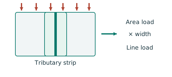
- Find the tributary width from the actual plan.
- Area load × tributary width gives load per beam length.
- A supporting beam receives the other beam’s end reaction.
Remember: A reaction becomes a point load, not automatically a UDL.
Half of each adjacent simply supported bay reaches column A. The hatch is a load-allocation area, not the column’s steel cross-sectional area. Both roof and floor use .
Animation labFollow the floor load in 3D
Supplement to the original lesson. Enable JavaScript to play, step through calculations and rotate 3D models. The following explanation remains readable offline.
- The floor carries pressure in . The highlighted strip belongs to one secondary beam.
- Multiply pressure by tributary width: . The illustration uses .
- A primary beam receives the secondary beam reaction at their connection, not a new full-span UDL.
- Trace reactions down to columns and foundations. Count each loaded area once.
2. Read the source’s floor-count reduction
| Floors carried | Over | ||||||||
|---|---|---|---|---|---|---|---|---|---|
| Imposed reduction | maximum |
The upper member supports one roof level → reduction. The lower supports roof plus first floor →two levels →. Retain of the cumulative imposed load below the floor. This is the rule applied by this lecture example, attributed there to the 2011 Dead and Imposed Loads Code; do not extend it automatically to an occupancy or question where reduction is disallowed. Dead load is not reduced.
Animation labFollow the floor load in 3D
Supplement to the original lesson. Enable JavaScript to play, step through calculations and rotate 3D models. The following explanation remains readable offline.
- The floor carries pressure in . The highlighted strip belongs to one secondary beam.
- Multiply pressure by tributary width: . The illustration uses .
- A primary beam receives the secondary beam reaction at their connection, not a new full-span UDL.
- Trace reactions down to columns and foundations. Count each loaded area once.
3. Compute characteristic and ultimate loads at each level
All self-weight is already included. The lower load uses the whole accumulated load rather than adding an already factored/reduced upper force to a separately reduced floor force.
Animation labFrom characteristic to design load
Supplement to the original lesson. Enable JavaScript to play, step through calculations and rotate 3D models. The following explanation remains readable offline.
- G is permanent load; Q is imposed load. A surface load and a line load also have different units.
- This illustration uses the course gravity case . Other combinations in the original text retain their own factors.
- For illustrative , change Q and watch each separate contribution.
- Do not carry this ULS total automatically into deflection. Follow the stated SLS load case.
4. Select and check the upper column
Simple explanation: A pinned beam can still bend its column
Its reaction can miss the column centre and create a lever arm.
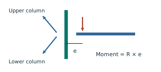
- Find the reaction’s actual nominal eccentricity.
- Multiply reaction by eccentricity to obtain the joint moment.
- Share that moment using the stated column-stiffness model.
Remember: Equal sharing needs equal relevant stiffness; it is not automatic.
Trial UC. Data File p.11 gives , , , , , . The original lecture uses the same area . , giving . Both ends are held in position but free to rotate, so , with both axes having .
The source uses rounded , so and prints . Exact interpolation gives ; both pass. The previously omitted major-axis comparison is provided above.
Animation labEffective length and buckling axes
Supplement to the original lesson. Enable JavaScript to play, step through calculations and rotate 3D models. The following explanation remains readable offline.
- A column can bow sideways before its section reaches the crushing resistance.
- Each axis has its own radius of gyration and restraint spacing.
- , with compatible length units. A tie affects only the directions it actually restrains.
- Select each buckling curve and compressive strength before forming Pc. The governing axis is determined by resistance, not slenderness alone.
5. Select and check the lower column
Simple explanation: The column needs more than one pass
A slice can be strong while the whole member still buckles.
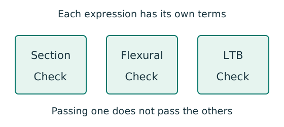
- Check cross-section compression plus bending.
- Then check the separate member-buckling expressions.
- Keep each moment, factor and resistance in its specified expression.
Remember: The three checks do not share interchangeable denominators.
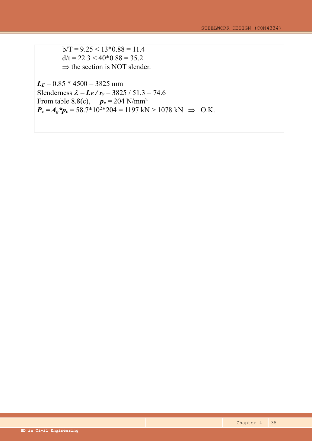
Trial UC. Data File p.11 gives , , , , , . The flange thickness again gives . The base is fixed; the floor end is held in position but free to rotate, so use the recommended factor .
The source rounds to , giving (printed ). Exact interpolation gives . Both selected columns pass the requested axial-only design; the lower weak-axis check is more highly utilised.
Animation labEffective length and buckling axes
Supplement to the original lesson. Enable JavaScript to play, step through calculations and rotate 3D models. The following explanation remains readable offline.
- A column can bow sideways before its section reaches the crushing resistance.
- Each axis has its own radius of gyration and restraint spacing.
- , with compatible length units. A tie affects only the directions it actually restrains.
- Select each buckling curve and compressive strength before forming Pc. The governing axis is determined by resistance, not slenderness alone.
Compact exam answer
. Roof / is /; lower-storey accumulation /. Upper-storey ultimate force ; lower-storey imposed load after reduction gives . Upper-storey UC: non-slender, , . Lower-storey UC: non-slender, , . Both are S355 with , governed by minor-axis curve c; both are adequate.
Mistakes to avoid
- Do not use or elevation heights when calculating tributary plan area.
- Include roof load in the lower segment.
- Reduce only imposed load and count the roof as instructed.
- Do not add self-weight twice.
- Use fixed/pinned recommended for the lower column, not the upper one.
Procedure for an unfamiliar variant
- Trace the loads above each column segment and keep dead/imposed components separate.
- Read actual storey heights, section properties and end restraints in both axes.
- For simple construction derive nominal eccentric moments and share them by .
- Classify the section and form the correct section and member resistances.
- Apply only the prescribed load reductions and moment amplification rules.
- Check every storey segment and report both the governing check and source assumptions.
Independent self-check
Try it yourself. Invented variant: imposed-load reduction is explicitly prohibited. Does the selected lower column still pass?
Reveal answer and reasoning
Lower force becomes . Compare with : utilisation, so it still passes. The roof segment is unchanged because it already had zero reduction.
Animation labEffective length and buckling axes
Supplement to the original lesson. Enable JavaScript to play, step through calculations and rotate 3D models. The following explanation remains readable offline.
- A column can bow sideways before its section reaches the crushing resistance.
- Each axis has its own radius of gyration and restraint spacing.
- , with compatible length units. A tie affects only the directions it actually restrains.
- Select each buckling curve and compressive strength before forming Pc. The governing axis is determined by resistance, not slenderness alone.