Column example 3: loads and eccentric moments in two storeys
Open “Animation lab” beside a teaching step for a visual explanation or a walkthrough of its original expressions. Models are illustrative; source answers remain unchanged.
← Read this lecture example beside its chapter concepts
Need a simpler picture? Open “Simple explanation” beside a difficult step. These optional notes do not replace the full solution.
Check UC S355 in a two-storey simple-construction column. The lower storey is , the upper . Use the supplied reaction table and stated construction assumptions, including a pinned base and moment amplification.
Original source: LectureNotes/Ch 4_Column.pdf — p. 25, p. 26, p. 27, p. 28, p. 29, p. 30, p. 31. Values tagged given are in the question or diagram; lookup values come from a named table; calculated values follow from the working; assumptions are stated explicitly.
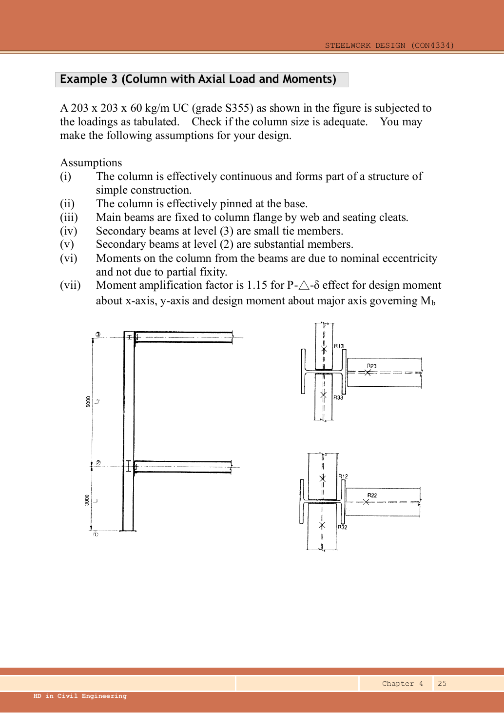
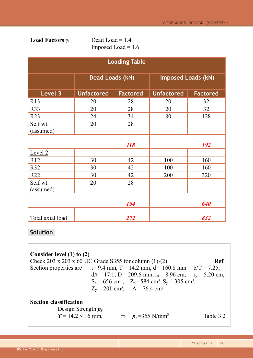
Read the diagram and collect the data
| Given model | Implication |
|---|---|
| Continuous column, simple beam construction | Use nominal eccentricity and moment sharing; all moment factors are . |
| Base effectively pinned | Lower segment has no base rotational fixity. Substantial level 2 members give the source’s upper restraint assumption. |
| Roof secondary beams are small ties | Provide positional but not rotational restraint for the upper column’s weak-axis buckling. |
| Main beams connect by web and seating cleats | Source adopts reaction line beyond the column face. |
| Self-weight | Source assumes characteristic dead self-weight at each level; include it once per level. |
| Section data | Data p.11: , , , , , , , , , , , , . |
Before calculating: recognition and strategy
There are two separate accounting tasks. Axial load accumulates down the column. Eccentric reactions create a net joint moment which is shared between the upper and lower column in proportion to . Equal opposite secondary reactions cancel their moments, but their vertical loads still add. Keep these operations separate. This solution retains arithmetic precision; a short comparison also explains the source’s rounded values.
1. Recalculate every reaction-table entry and storey total
| Level/reaction | Given () | Given () | Ultimate total | ||
|---|---|---|---|---|---|
| 3: | |||||
| 3: | |||||
| 3: | |||||
| 3: assumed self-weight | |||||
| 3 totals | |||||
| 2: | |||||
| 2: | |||||
| 2: | |||||
| 2: assumed self-weight | |||||
| 2 added totals |
Animation labFrom characteristic to design load
Supplement to the original lesson. Enable JavaScript to play, step through calculations and rotate 3D models. The following explanation remains readable offline.
- G is permanent load; Q is imposed load. A surface load and a line load also have different units.
- This illustration uses the course gravity case . Other combinations in the original text retain their own factors.
- For illustrative , change Q and watch each separate contribution.
- Do not carry this ULS total automatically into deflection. Follow the stated SLS load case.
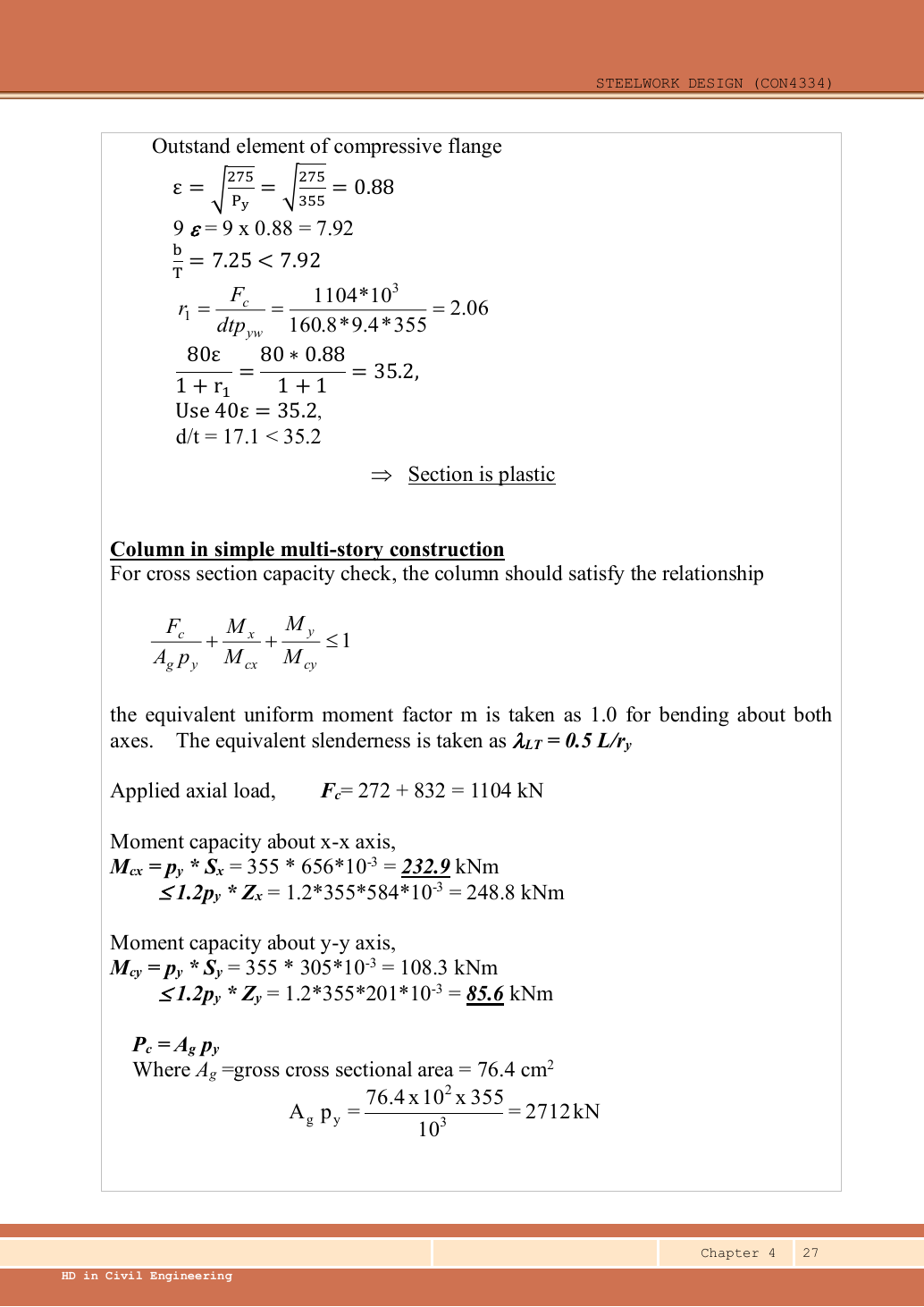
2. Strength and section classification
The lower section’s larger axial compression is sufficient for checking this section’s worst compression/bending web limit. The selected section has the same geometry throughout both storeys.
Animation labWhy thin elements buckle locally
Supplement to the original lesson. Enable JavaScript to play, step through calculations and rotate 3D models. The following explanation remains readable offline.
- The flange outstand and web have different widths, thicknesses and edge support conditions.
- A thinner plate can wrinkle locally before the complete member loses stability.
- Class 1 allows plastic rotation; Class 2 reaches plastic resistance; Class 3 reaches elastic resistance; Class 4 requires effective properties.
- Check every relevant compression element with the supplied limits and stress distribution. The deformation shown is qualitative.
3. Calculate section and elastic member capacities
The linear section interaction uses and . The member interaction uses and . The source reuses similar notation for different definitions; keep a clearly labelled capacity list.
Animation labCompression and tension across a section
Supplement to the original lesson. Enable JavaScript to play, step through calculations and rotate 3D models. The following explanation remains readable offline.
- For sagging, the top flange is in compression and the bottom in tension; hogging reverses this.
- Elastic bending stress varies with distance from the neutral axis: .
- The section class governs whether elastic, plastic or effective properties may be used.
- Use the shear at the section under examination; the largest shear elsewhere is not automatically coexistent.
4. Nominal eccentricity and stiffness sharing at level 2
Simple explanation: A pinned beam can still bend its column
Its reaction can miss the column centre and create a lever arm.
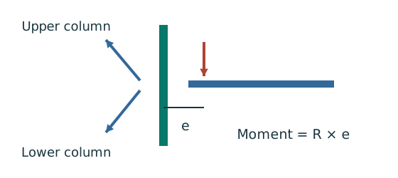
- Find the reaction’s actual nominal eccentricity.
- Multiply reaction by eccentricity to obtain the joint moment.
- Share that moment using the stated column-stiffness model.
Remember: Equal sharing needs equal relevant stiffness; it is not automatic.
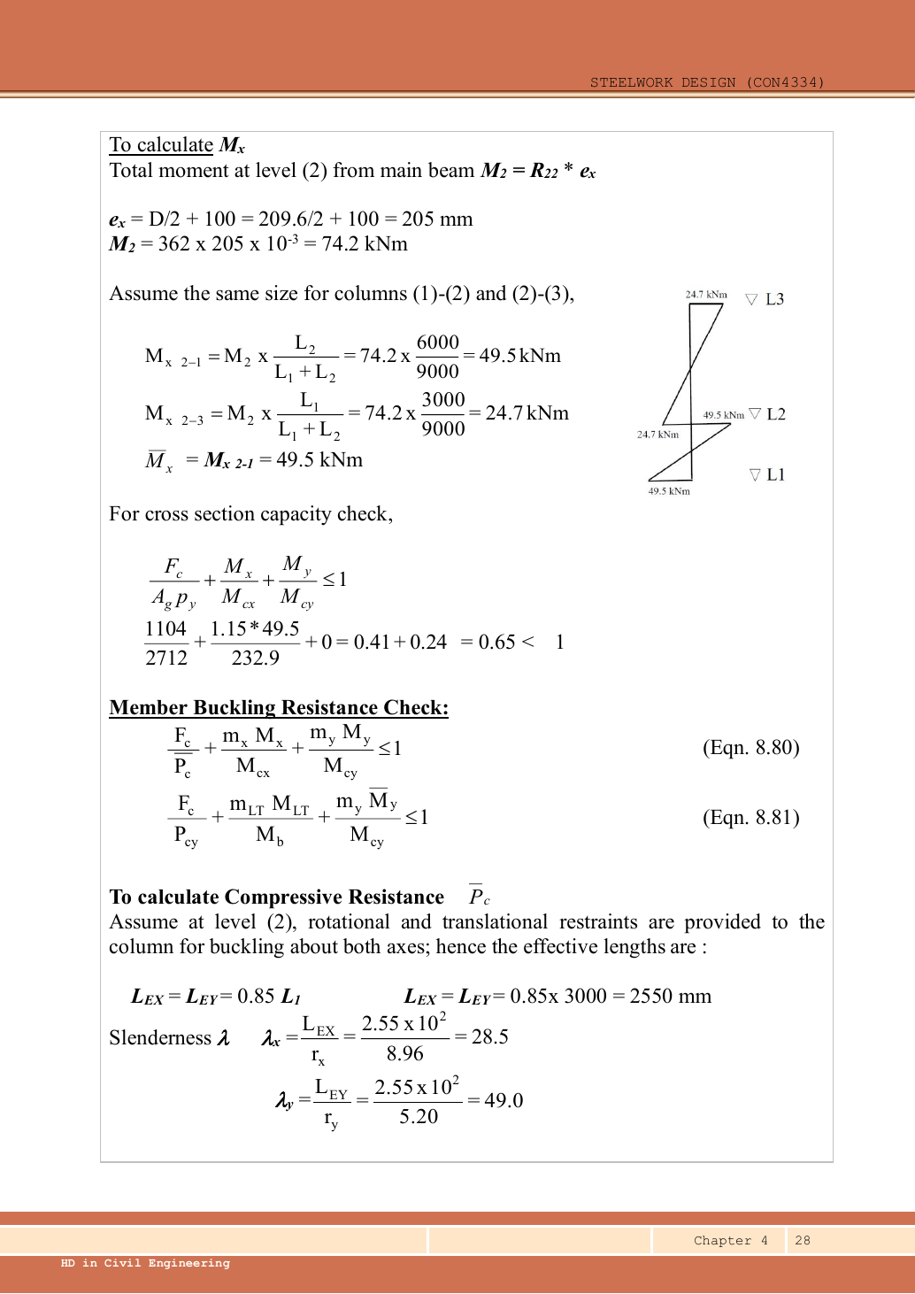
The main beam reaction acts on one flange. takes us from the centroid to the flange face; the nominal then takes us to the source’s reaction line. and have equal magnitudes on opposite sides, so their minor-axis nominal moments cancel.
The lower storey is shorter, hence stiffer and receives the larger moment share. The source rounds to , to and shares to /. The little moment diagrams on p.28 show the moment components associated with this joint sharing; they are not additional applied point loads.
Animation labEccentric reactions and stiffness sharing
Supplement to the original lesson. Enable JavaScript to play, step through calculations and rotate 3D models. The following explanation remains readable offline.
- A beam reaction can act away from the column centre even at a nominally pinned beam connection.
- . Opposing reactions can cancel part of the signed moment, while both still add compression.
- The course simple model distributes the joint moment in proportion to of the columns above and below.
- Equal relevant stiffness gives half each. A roof joint with no upper column is a different case.
5. Lower-storey section interaction
Simple explanation: The column needs more than one pass
A slice can be strong while the whole member still buckles.
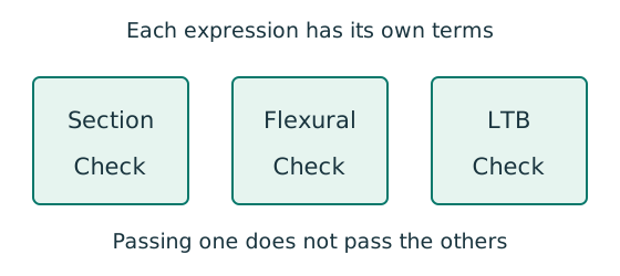
- Check cross-section compression plus bending.
- Then check the separate member-buckling expressions.
- Keep each moment, factor and resistance in its specified expression.
Remember: The three checks do not share interchangeable denominators.
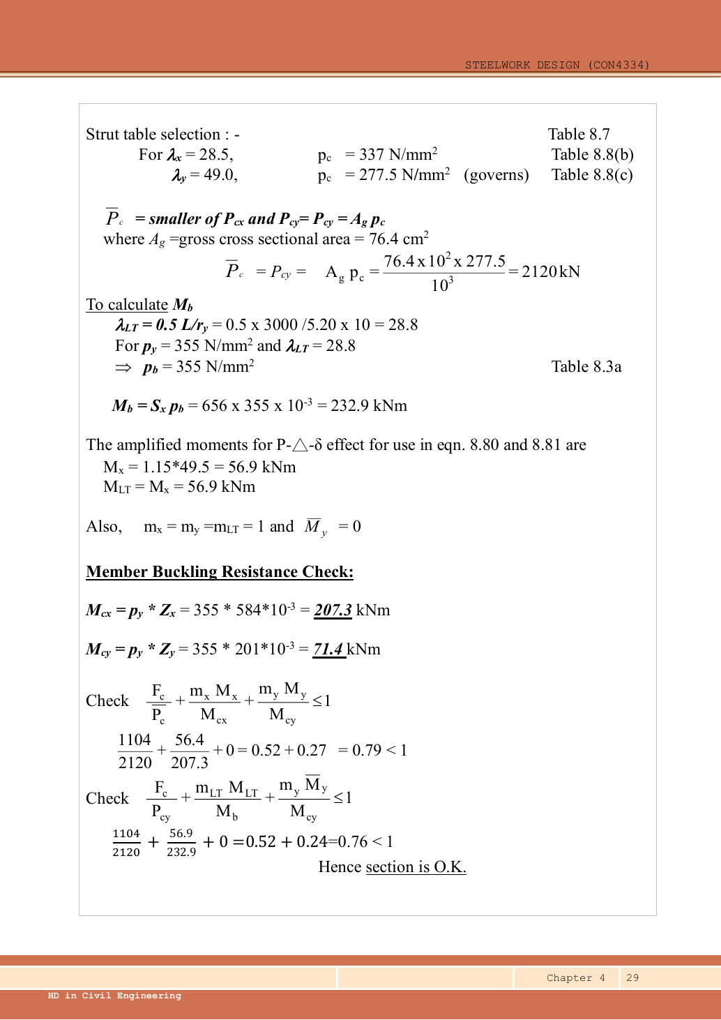
Using the rounded source loads and moments gives . Both precision levels agree with the source result of approximately .
Animation labA strong slice can belong to an unstable member
Supplement to the original lesson. Enable JavaScript to play, step through calculations and rotate 3D models. The following explanation remains readable offline.
- Combine axial compression and the two bending demands using the specified section resistances.
- The whole member adds effective-length and buckling-curve effects.
- This uses its own moment factor and bending resistance; it is not a copy of the section check.
- Elastic, plastic and buckling resistances are not interchangeable. Read the three original expressions and their first-order/amplified moments.
6. Lower-storey member buckling
Simple explanation: Why a long column can fail before crushing
Push a long thin ruler from both ends: it may bow sideways first.
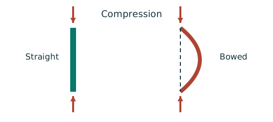
- Find effective length and radius of gyration for each axis.
- Calculate slenderness for both directions.
- Use the appropriate buckling curve before forming resistance.
Remember: Compare the final resistances; slenderness alone may not identify the controlling axis.
The source assumes rotational and positional restraint at level 2 in both axes; the base is pinned. Table 8.6 recommended fixed/pinned factor is . Use that assumed model explicitly, rather than inferring a rigid base from the drawing’s plate line.
Simple construction sets all factors to . For bending buckling use actual storey length , not :
Animation labA strong slice can belong to an unstable member
Supplement to the original lesson. Enable JavaScript to play, step through calculations and rotate 3D models. The following explanation remains readable offline.
- Combine axial compression and the two bending demands using the specified section resistances.
- The whole member adds effective-length and buckling-curve effects.
- This uses its own moment factor and bending resistance; it is not a copy of the section check.
- Elastic, plastic and buckling resistances are not interchangeable. Read the three original expressions and their first-order/amplified moments.
7. Upper-storey governing moment and section interaction
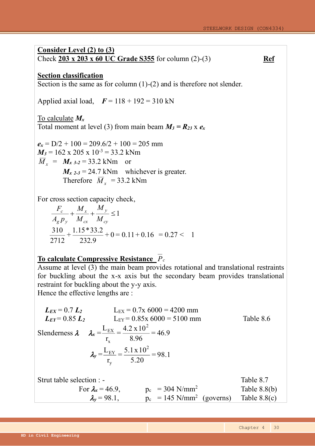
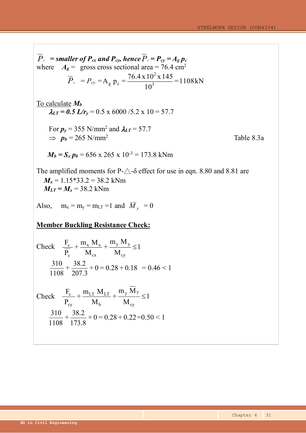
The upper-storey moment is governed by the roof reaction, not automatically the moment inherited at level 2. The source uses , giving amplified . Its printed comes from early rounding of the separate utilisation terms; full arithmetic is about at two decimal places.
Animation labA strong slice can belong to an unstable member
Supplement to the original lesson. Enable JavaScript to play, step through calculations and rotate 3D models. The following explanation remains readable offline.
- Combine axial compression and the two bending demands using the specified section resistances.
- The whole member adds effective-length and buckling-curve effects.
- This uses its own moment factor and bending resistance; it is not a copy of the section check.
- Elastic, plastic and buckling resistances are not interchangeable. Read the three original expressions and their first-order/amplified moments.
8. Upper-storey buckling about both axes
The main roof beam supplies the source’s major-axis rotational restraint. The small secondary roof ties only restrain position in the weak direction. With level 2 restrained, the lecture uses for and for .
Both storeys pass all three demonstrated interaction checks. The lower-storey flexural interaction, approximately , is the largest. The original source-rounded results are approximately lower // and upper //.
Animation labA strong slice can belong to an unstable member
Supplement to the original lesson. Enable JavaScript to play, step through calculations and rotate 3D models. The following explanation remains readable offline.
- Combine axial compression and the two bending demands using the specified section resistances.
- The whole member adds effective-length and buckling-curve effects.
- This uses its own moment factor and bending resistance; it is not a copy of the section check.
- Elastic, plastic and buckling resistances are not interchangeable. Read the three original expressions and their first-order/amplified moments.
Compact exam answer
Using exact arithmetic: upper/lower compression /. pᵧ355,Class 1; A𝗀pᵧ2,712.2 kN; section capacities /; elastic /. ; level 2 moment shares /. Amplified lower moment ; upper governing . Lower ,Mᵦ232.88; interactions //. Upper ,Mᵦ173.7391; interactions //. Both storeys adequate under the stated simple-construction restraint assumptions.
Mistakes to avoid
- Accumulate both levels for lower axial load.
- Cancel opposite moments, not the underlying compressive reactions.
- Share moment by , not equally and not by axial-force ratios.
- Use actual storey length in 0.5L/rᵧ.
- Do not treat a small roof tie as rotational restraint.
Procedure for an unfamiliar variant
- Trace the loads above each column segment and keep dead/imposed components separate.
- Read actual storey heights, section properties and end restraints in both axes.
- For simple construction derive nominal eccentric moments and share them by .
- Classify the section and form the correct section and member resistances.
- Apply only the prescribed load reductions and moment amplification rules.
- Check every storey segment and report both the governing check and source assumptions.
Independent self-check
Try it yourself. Invented variant: change only the upper-storey length from to , retaining the same column section and level 2 moment . How is that joint moment shared?
Reveal answer and reasoning
The upper and lower values now match, so each receives . The lower amplified share becomes . This redistribution does not alter the accumulated axial loads. Upper buckling lengths and 0.5L/rᵧ also change and must be recalculated; the original upper resistance cannot be reused.
Animation labEccentric reactions and stiffness sharing
Supplement to the original lesson. Enable JavaScript to play, step through calculations and rotate 3D models. The following explanation remains readable offline.
- A beam reaction can act away from the column centre even at a nominally pinned beam connection.
- . Opposing reactions can cancel part of the signed moment, while both still add compression.
- The course simple model distributes the joint moment in proportion to of the columns above and below.
- Equal relevant stiffness gives half each. A roof joint with no upper column is a different case.