Column example 2: a weak-axis tie permits a lighter section
Open “Animation lab” beside a teaching step for a visual explanation or a walkthrough of its original expressions. Models are illustrative; source answers remain unchanged.
← Read this lecture example beside its chapter concepts
Need a simpler picture? Open “Simple explanation” beside a difficult step. These optional notes do not replace the full solution.
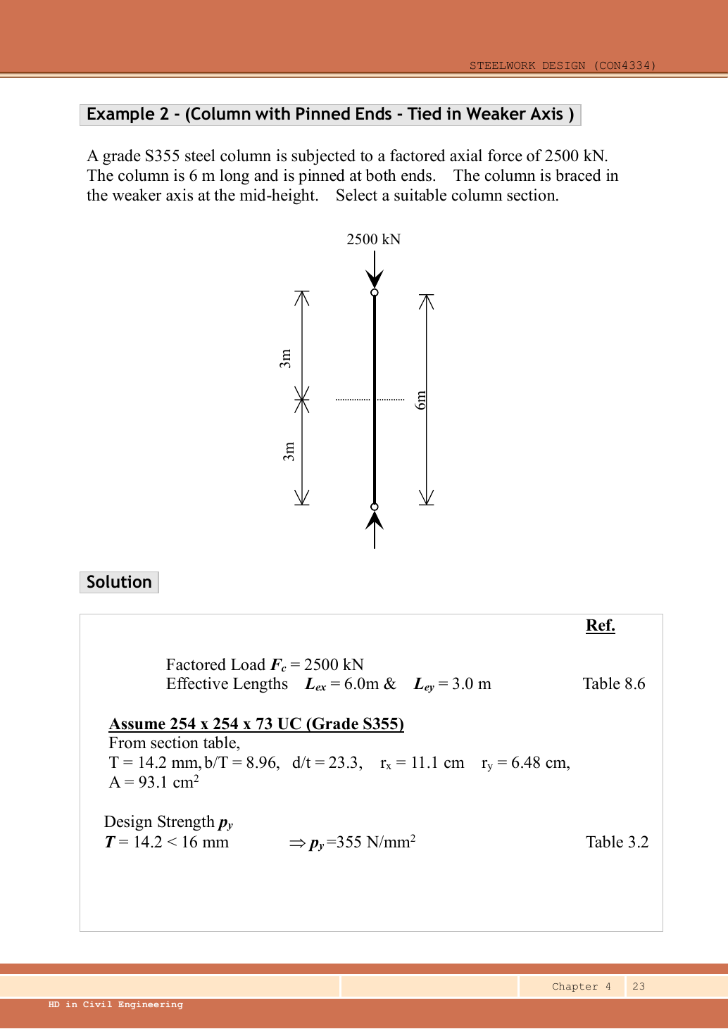
Repeat the axial-column design with a pinned column and an effective midheight tie against weak-axis buckling. Select and check a Grade S355 UC.
Original source: LectureNotes/Ch 4_Column.pdf — p. 23, p. 24. Values tagged given are in the question or diagram; lookup values come from a named table; calculated values follow from the working; assumptions are stated explicitly.
Read the diagram and collect the data
| Input | Origin |
|---|---|
| Axial force | Given design compression. |
| Direction of tie | Question states weak direction: shorten -axis buckling length only. |
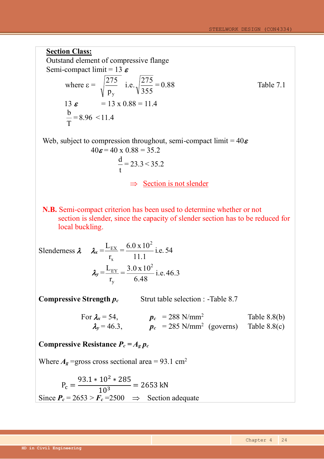
| Trial section | Data File p.11, UC: , , , , , . |
| Tables | pᵧ355 because ; rolled H uses curves b/c. |
Before calculating: recognition and strategy
Compare this to Example 1: restraints can be as important as area. The weak-axis tie reduces its unbraced length from to . A smaller column is now possible, but after changing section both radii, the area and the thickness-dependent strength must be reread. Do not reuse Example 1’s section properties.
1. Set each effective length
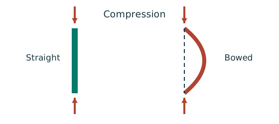
Simple explanation: Why a long column can fail before crushing
Push a long thin ruler from both ends: it may bow sideways first.
- Find effective length and radius of gyration for each axis.
- Calculate slenderness for both directions.
- Use the appropriate buckling curve before forming resistance.
Remember: Compare the final resistances; slenderness alone may not identify the controlling axis.
A horizontal positional restraint suppresses a buckling displacement. It does not support half the vertical load or create a new compression case.
Animation labEffective length and buckling axes
Supplement to the original lesson. Enable JavaScript to play, step through calculations and rotate 3D models. The following explanation remains readable offline.
- A column can bow sideways before its section reaches the crushing resistance.
- Each axis has its own radius of gyration and restraint spacing.
- , with compatible length units. A tie affects only the directions it actually restrains.
- Select each buckling curve and compressive strength before forming Pc. The governing axis is determined by resistance, not slenderness alone.
2. Trial UC
These values come from the same exact section row on Data File p.11. This lighter trial is the one selected in the lecture.
Animation labEffective length and buckling axes
Supplement to the original lesson. Enable JavaScript to play, step through calculations and rotate 3D models. The following explanation remains readable offline.
- A column can bow sideways before its section reaches the crushing resistance.
- Each axis has its own radius of gyration and restraint spacing.
- , with compatible length units. A tie affects only the directions it actually restrains.
- Select each buckling curve and compressive strength before forming Pc. The governing axis is determined by resistance, not slenderness alone.
3. Check local slenderness
Animation labWhy thin elements buckle locally
Supplement to the original lesson. Enable JavaScript to play, step through calculations and rotate 3D models. The following explanation remains readable offline.
- The flange outstand and web have different widths, thicknesses and edge support conditions.
- A thinner plate can wrinkle locally before the complete member loses stability.
- Class 1 allows plastic rotation; Class 2 reaches plastic resistance; Class 3 reaches elastic resistance; Class 4 requires effective properties.
- Check every relevant compression element with the supplied limits and stress distribution. The deformation shown is qualitative.
4. Slenderness for the tied and untied directions
Now exceeds . That alone does not prove the axis controls because its curve b is more favourable than the weak-axis curve c.
Animation labEffective length and buckling axes
Supplement to the original lesson. Enable JavaScript to play, step through calculations and rotate 3D models. The following explanation remains readable offline.
- A column can bow sideways before its section reaches the crushing resistance.
- Each axis has its own radius of gyration and restraint spacing.
- , with compatible length units. A tie affects only the directions it actually restrains.
- Select each buckling curve and compressive strength before forming Pc. The governing axis is determined by resistance, not slenderness alone.
5. Interpolate each curve
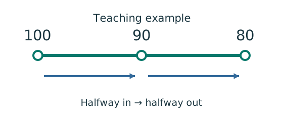
Simple explanation: A value between two table rows
Move the same fraction of the way across both number ranges.
- Choose the correct table, curve and strength column first.
- Find how far your input lies between the two rows.
- Apply that fraction to the change between their answers.
Remember: Teaching example: halfway between outputs 100 and 80 gives 90.
Use Table 8.8(b), pᵧ355 for and Table 8.8(c), pᵧ355 for .
Despite its smaller slenderness, the weak axis gives the slightly smaller strength. The source values and are rounded representations.
Animation labEffective length and buckling axes
Supplement to the original lesson. Enable JavaScript to play, step through calculations and rotate 3D models. The following explanation remains readable offline.
- A column can bow sideways before its section reaches the crushing resistance.
- Each axis has its own radius of gyration and restraint spacing.
- , with compatible length units. A tie affects only the directions it actually restrains.
- Select each buckling curve and compressive strength before forming Pc. The governing axis is determined by resistance, not slenderness alone.
6. Check the controlling resistance
The original rounds to , giving , printed . The exact interpolation gives . The tie makes the trial adequate where the untied example used . This conclusion assumes the tie provides the stated effective restraint; tie design itself is not part of this question.
Animation labEffective length and buckling axes
Supplement to the original lesson. Enable JavaScript to play, step through calculations and rotate 3D models. The following explanation remains readable offline.
- A column can bow sideways before its section reaches the crushing resistance.
- Each axis has its own radius of gyration and restraint spacing.
- , with compatible length units. A tie affects only the directions it actually restrains.
- Select each buckling curve and compressive strength before forming Pc. The governing axis is determined by resistance, not slenderness alone.
Compact exam answer
Use S355 UC,; under the , limits, it is non-slender., ; , . Curves b/c give , . , adequate. Rounded source resistance .
Mistakes to avoid
- The tie changes only its effective buckling direction.
- Use the full axial force in both portions.
- Compare actual values, not slenderness alone.
- Reclassify after selecting a lighter section.
Procedure for an unfamiliar variant
- Identify axial load, any moments, actual length and restraints in each axis.
- Choose/read a section and confirm strength from the actual thickness.
- Check the appropriate flange and web local-slenderness limits.
- Find and separately; select each axis curve and interpolate .
- Calculate both axial resistances and identify the governing axis.
- If moments exist, complete section, flexural and axial/LTB interactions using their own capacities and moment definitions.
Independent self-check
Try it yourself. Invented variant: remove the weak-axis tie but retain UC. Find the weak-axis slenderness and estimate its supplied-table resistance.
Reveal answer and reasoning
. Curve c,pᵧ355: row gives and gives , so . , much less than . The untied version fails.
Animation labEffective length and buckling axes
Supplement to the original lesson. Enable JavaScript to play, step through calculations and rotate 3D models. The following explanation remains readable offline.
- A column can bow sideways before its section reaches the crushing resistance.
- Each axis has its own radius of gyration and restraint spacing.
- , with compatible length units. A tie affects only the directions it actually restrains.
- Select each buckling curve and compressive strength before forming Pc. The governing axis is determined by resistance, not slenderness alone.