Column example 1: a pinned column in axial compression
Open “Animation lab” beside a teaching step for a visual explanation or a walkthrough of its original expressions. Models are illustrative; source answers remain unchanged.
← Read this lecture example beside its chapter concepts
Need a simpler picture? Open “Simple explanation” beside a difficult step. These optional notes do not replace the full solution.
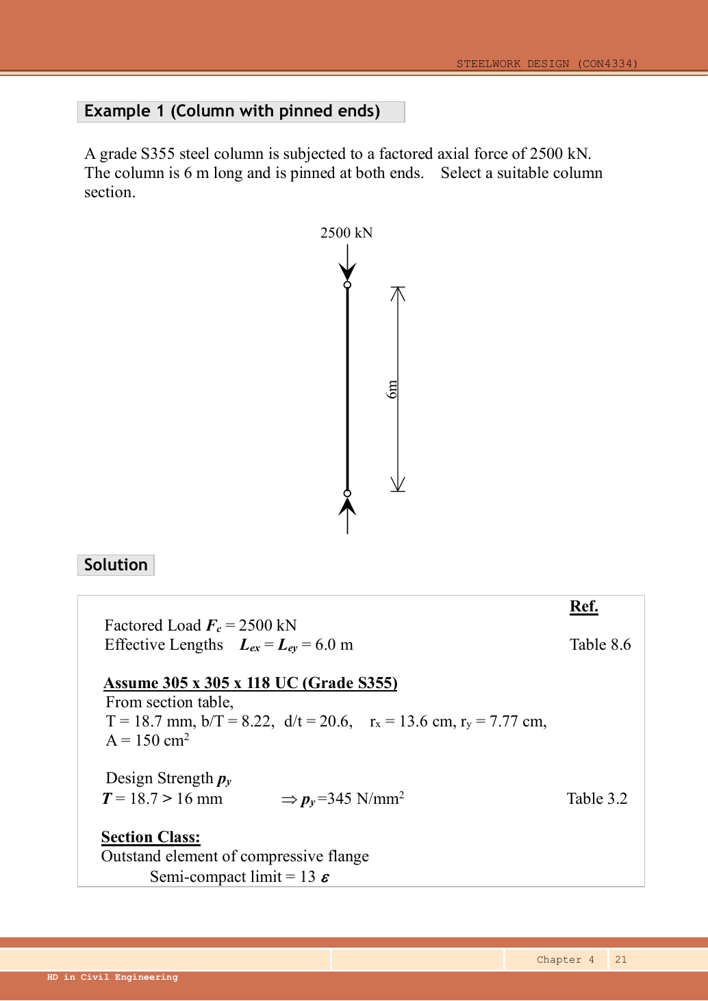
Select a Grade S355 UC for a column pinned at both ends, carrying a design axial compression of . Check the selected section’s compression resistance.
Original source: LectureNotes/Ch 4_Column.pdf — p. 21, p. 22. Values tagged given are in the question or diagram; lookup values come from a named table; calculated values follow from the working; assumptions are stated explicitly.
Read the diagram and collect the data
| Input | Source and meaning |
|---|---|
| Design load | Given , already factored; no dead/imposed breakdown is needed. |
| Restraints | Pinned-pinned, translation prevented at ends; Table 8.6 gives in both axes. |
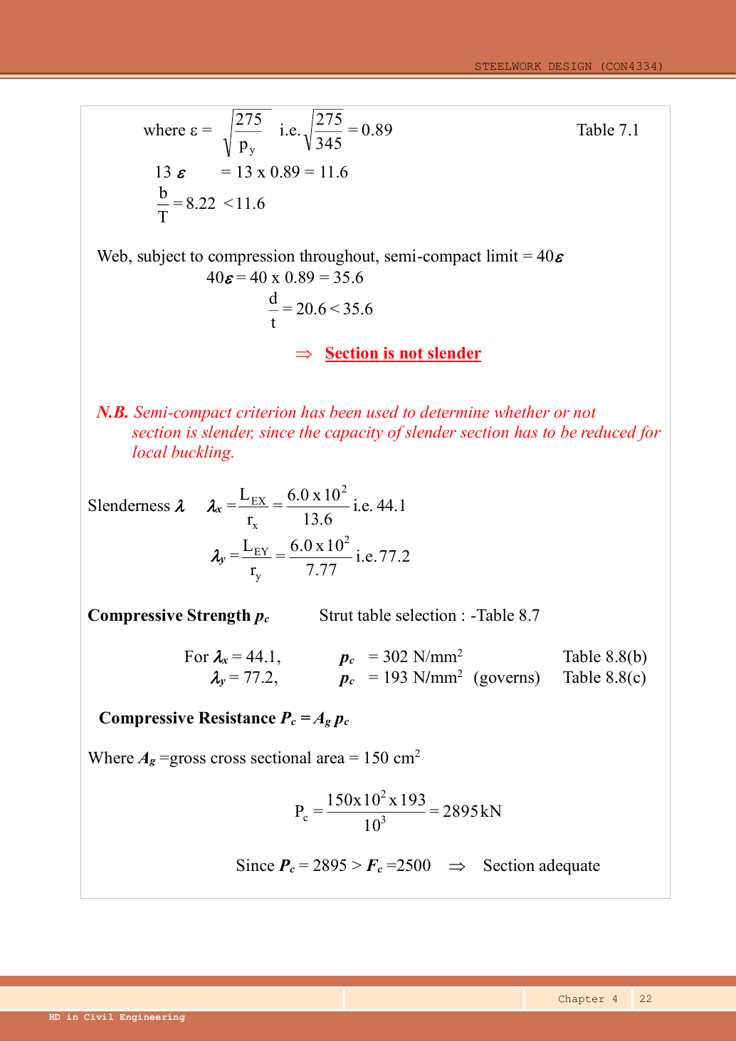
| Selected row | Data File p.11, UC: flange , , , , , . |
| Strength and curves | S355,, giving . Hot-rolled H-section, , so axis uses curve b; axis uses curve c. |
Before calculating: recognition and strategy
There is no stated bending moment, so the core numerical task is axial member buckling. First ensure the local plates are not slender, allowing gross area. Then calculate both axis slendernesses and select the correct curve for each. The area alone is not enough: a long weak column can buckle well before reaching A𝗀pᵧ.
1. Choose a section and confirm its strength
The lecturer selects a trial UC. Its nominal mass is part of the section designation. The strength calculation uses the tabulated gross area . The flange thickness is , falling within the S355 thickness band .
exceeds the load but is not the member resistance. Proceed to local-slenderness and overall-buckling checks.
Animation labEffective length and buckling axes
Supplement to the original lesson. Enable JavaScript to play, step through calculations and rotate 3D models. The following explanation remains readable offline.
- A column can bow sideways before its section reaches the crushing resistance.
- Each axis has its own radius of gyration and restraint spacing.
- , with compatible length units. A tie affects only the directions it actually restrains.
- Select each buckling curve and compressive strength before forming Pc. The governing axis is determined by resistance, not slenderness alone.
2. Establish a non-slender section
Simple explanation: A thin part can wrinkle first
A thin plate may wrinkle before the whole steel member reaches its intended resistance.
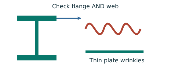
- Check flange and web slenderness using their own definitions.
- Compare each ratio with the correct class limits.
- The less favourable element determines the section class.
Remember: Bending limits and uniform-compression limits are different.
This establishes Class 3 or better, not necessarily a plastic flange. The pure-compression example does not need plastic bending resistance; checking the non-slender boundary is sufficient for its stated method.
Animation labWhy thin elements buckle locally
Supplement to the original lesson. Enable JavaScript to play, step through calculations and rotate 3D models. The following explanation remains readable offline.
- The flange outstand and web have different widths, thicknesses and edge support conditions.
- A thinner plate can wrinkle locally before the complete member loses stability.
- Class 1 allows plastic rotation; Class 2 reaches plastic resistance; Class 3 reaches elastic resistance; Class 4 requires effective properties.
- Check every relevant compression element with the supplied limits and stress distribution. The deformation shown is qualitative.
3. Calculate slenderness about both axes
Simple explanation: Why a long column can fail before crushing
Push a long thin ruler from both ends: it may bow sideways first.
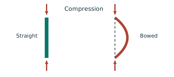
- Find effective length and radius of gyration for each axis.
- Calculate slenderness for both directions.
- Use the appropriate buckling curve before forming resistance.
Remember: Compare the final resistances; slenderness alone may not identify the controlling axis.
The smaller weak-axis radius makes its slenderness much larger. Still read both curves rather than assuming the larger slenderness by itself proves which resistance controls.
Animation labEffective length and buckling axes
Supplement to the original lesson. Enable JavaScript to play, step through calculations and rotate 3D models. The following explanation remains readable offline.
- A column can bow sideways before its section reaches the crushing resistance.
- Each axis has its own radius of gyration and restraint spacing.
- , with compatible length units. A tie affects only the directions it actually restrains.
- Select each buckling curve and compressive strength before forming Pc. The governing axis is determined by resistance, not slenderness alone.
4. Read and interpolate the two compressive strengths
Simple explanation: A table lookup needs several keys
A table is like an address: knowing only the street is not enough.
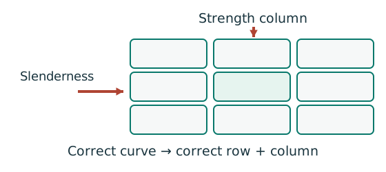
- Select the curve using section type, thickness and axis.
- Select the material-strength column.
- Bracket the slenderness and interpolate if required.
Remember: Do not jump between steel grades or extrapolate past supplied data.
Table 8.7, rolled H section with maximum thickness : uses 8.8(b), uses 8.8(c). In each use the pᵧ=345 column of Data File p.8.
The source rounds these to and . The minor axis has the smaller and controls for the same area.
Animation labEffective length and buckling axes
Supplement to the original lesson. Enable JavaScript to play, step through calculations and rotate 3D models. The following explanation remains readable offline.
- A column can bow sideways before its section reaches the crushing resistance.
- Each axis has its own radius of gyration and restraint spacing.
- , with compatible length units. A tie affects only the directions it actually restrains.
- Select each buckling curve and compressive strength before forming Pc. The governing axis is determined by resistance, not slenderness alone.
5. Form resistances and conclude
Using the lecturer’s rounded gives , agreeing with the original answer. The governing failure mode is minor-axis overall buckling, not yielding of the full gross area.
Animation labEffective length and buckling axes
Supplement to the original lesson. Enable JavaScript to play, step through calculations and rotate 3D models. The following explanation remains readable offline.
- A column can bow sideways before its section reaches the crushing resistance.
- Each axis has its own radius of gyration and restraint spacing.
- , with compatible length units. A tie affects only the directions it actually restrains.
- Select each buckling curve and compressive strength before forming Pc. The governing axis is determined by resistance, not slenderness alone.
Compact exam answer
Select S355 UC; , giving . ,, non-slender.,,. Curves b/c give respectively , . , adequate. Rounded source result .
Mistakes to avoid
- Do not use solely because the steel is S355.
- Do not halve the effective length just because both ends are supported.
- Do not use the same strut curve for both UC axes.
- Do not treat the lower reaction arrow as a second applied load.
Procedure for an unfamiliar variant
- Identify axial load, any moments, actual length and restraints in each axis.
- Choose/read a section and confirm strength from the actual thickness.
- Check the appropriate flange and web local-slenderness limits.
- Find and separately; select each axis curve and interpolate .
- Calculate both axial resistances and identify the governing axis.
- If moments exist, complete section, flexural and axial/LTB interactions using their own capacities and moment definitions.
Independent self-check
Try it yourself. Invented variant: the same column now carries design axial compression, with the same length and restraints. Does it pass?
Reveal answer and reasoning
No. Non-slender classification and buckling resistance are unchanged. Utilisation. The gross squash resistance cannot override the member buckling failure.
Animation labEffective length and buckling axes
Supplement to the original lesson. Enable JavaScript to play, step through calculations and rotate 3D models. The following explanation remains readable offline.
- A column can bow sideways before its section reaches the crushing resistance.
- Each axis has its own radius of gyration and restraint spacing.
- , with compatible length units. A tie affects only the directions it actually restrains.
- Select each buckling curve and compressive strength before forming Pc. The governing axis is determined by resistance, not slenderness alone.