Beam example 4: a tight LTB check with three point loads
Open “Animation lab” beside a teaching step for a visual explanation or a walkthrough of its original expressions. Models are illustrative; source answers remain unchanged.
← Read this lecture example beside its chapter concepts
Need a simpler picture? Open “Simple explanation” beside a difficult step. These optional notes do not replace the full solution.
Select/check a S355 simply supported beam of span carrying three characteristic point loads, each dead plus imposed, and a dead UDL. Loading is normal. Ends are restrained against torsion, with compression flange free to rotate in plan; there is no intermediate lateral restraint.
Original source: LectureNotes/Ch 3_Beam.pdf — p. 31, p. 32, p. 33. Values tagged given are in the question or diagram; lookup values come from a named table; calculated values follow from the working; assumptions are stated explicitly.
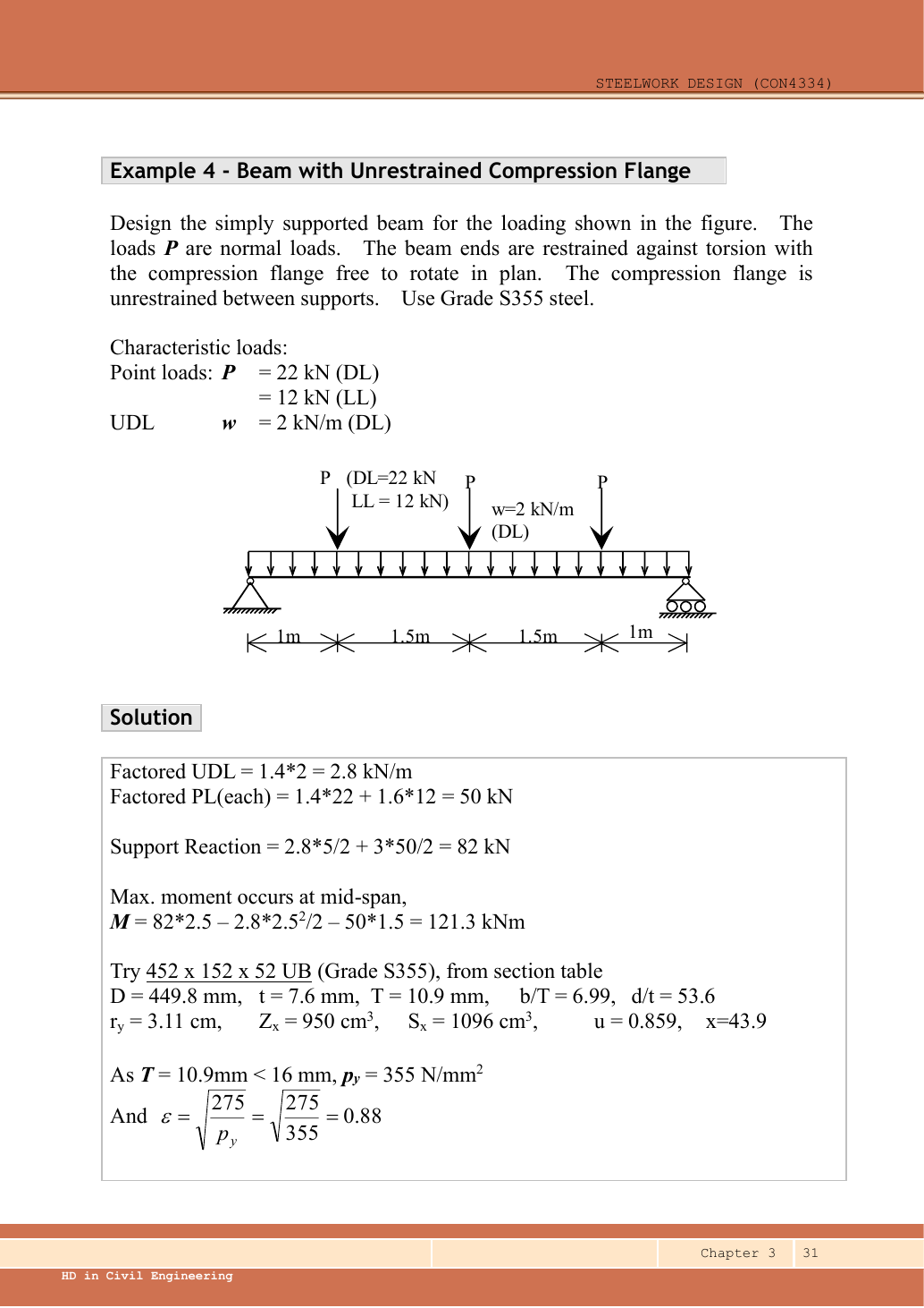
Read the diagram and collect the data
| Input | Source/use |
|---|---|
| Span and load positions | Given dimension chain; central point is at . |
| Lateral model | The question specifies normal loading, end torsional restraint and free in-plane rotation, so . |
| Trial section | The source properties correspond to UB: , , , , , , , , , . |
| Table source | Data File pp.9–10 exact section row; p.5 Table 8.3a strength; p.6 moment factors. |
Before calculating: recognition and strategy
Symmetry makes analysis simple but does not provide lateral restraint. Check the entire length for LTB. Because there are several point loads plus a UDL, the general quarter-point moment factor is appropriate. The result is close to the resistance, so use actual and and interpolate without early rounding.
1. Ultimate loading
Animation labFrom characteristic to design load
Supplement to the original lesson. Enable JavaScript to play, step through calculations and rotate 3D models. The following explanation remains readable offline.
- G is permanent load; Q is imposed load. A surface load and a line load also have different units.
- This illustration uses the course gravity case . Other combinations in the original text retain their own factors.
- For illustrative , change Q and watch each separate contribution.
- Do not carry this ULS total automatically into deflection. Follow the stated SLS load case.
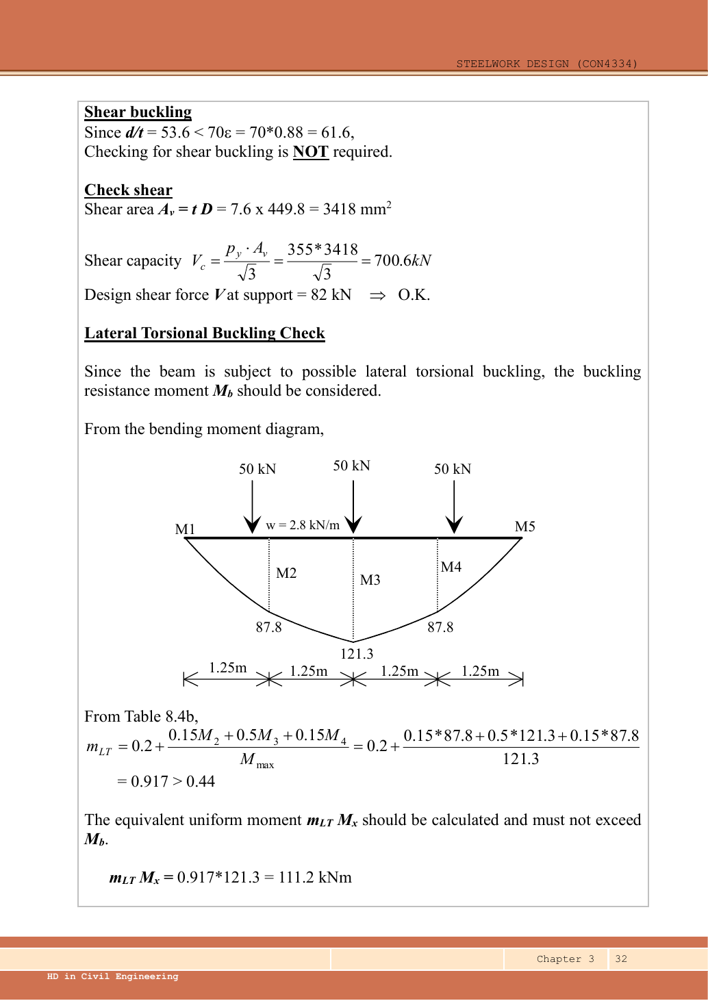
2. Reactions, moment and quarter-point ordinates
Simple explanation: Why reactions balance the loads
Think of a seesaw that must neither fall nor turn.
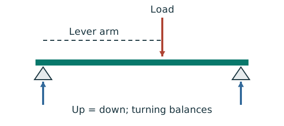
- Upward and downward forces must balance.
- Take moments about a support to eliminate its reaction.
- Use perpendicular distance from the point to the force line.
Remember: A lateral restraint is not automatically a vertical support.
The lower three-quarter point is at . The equality to follows from the symmetric loading; alternatively include both loads to its left in the free body. No moment contribution is assigned to a load lying to the right of the cut.
Animation labRead the moment shape within one segment
Supplement to the original lesson. Enable JavaScript to play, step through calculations and rotate 3D models. The following explanation remains readable offline.
- Moment ordinates must belong to the same effective unbraced segment.
- Same-side and reverse-curvature diagrams have different signed end ratios.
- The markers show ¼, ½ and ¾ of this segment, not of the entire beam.
- LTB and column flexural factors are different. Preserve their individual bounds and coefficient sets.
3. Trial section and section moment capacity
A small section satisfying M/pᵧ alone would not necessarily pass LTB. The chosen section is a verified trial, not a proof that every lighter section fails.
Animation labCompression and tension across a section
Supplement to the original lesson. Enable JavaScript to play, step through calculations and rotate 3D models. The following explanation remains readable offline.
- For sagging, the top flange is in compression and the bottom in tension; hogging reverses this.
- Elastic bending stress varies with distance from the neutral axis: .
- The section class governs whether elastic, plastic or effective properties may be used.
- Use the shear at the section under examination; the largest shear elsewhere is not automatically coexistent.
4. Section class and shear-web threshold
Animation labWhy thin elements buckle locally
Supplement to the original lesson. Enable JavaScript to play, step through calculations and rotate 3D models. The following explanation remains readable offline.
- The flange outstand and web have different widths, thicknesses and edge support conditions.
- A thinner plate can wrinkle locally before the complete member loses stability.
- Class 1 allows plastic rotation; Class 2 reaches plastic resistance; Class 3 reaches elastic resistance; Class 4 requires effective properties.
- Check every relevant compression element with the supplied limits and stress distribution. The deformation shown is qualitative.
5. Shear and low-shear bending applicability
Animation labSee shear in the web
Supplement to the original lesson. Enable JavaScript to play, step through calculations and rotate 3D models. The following explanation remains readable offline.
- Internal shear keeps the two sides of the cut in vertical equilibrium.
- For the course’s common I-section case, the web provides the principal shear area; use the specified definition.
- A slender web may require a different shear-buckling route before a simple shear-resistance formula is used.
- Use where applicable in the course. Convert N to kN before comparing with design shear.
6. Equivalent moment from Table 8.4b
Simple explanation: Why the shape of the moment diagram matters
The same peak moment is more demanding when a long region stays near that peak.
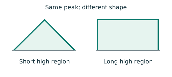
- Use the diagram of this unrestrained segment.
- Choose the applicable course sketch or quarter-point rule.
- Apply its factor to the demand, following the stated check.
Remember: Column flexural-buckling factors and LTB factors are not interchangeable.
This factor applies to member LTB only. The cross-section still must carry the actual .
Animation labRead the moment shape within one segment
Supplement to the original lesson. Enable JavaScript to play, step through calculations and rotate 3D models. The following explanation remains readable offline.
- Moment ordinates must belong to the same effective unbraced segment.
- Same-side and reverse-curvature diagrams have different signed end ratios.
- The markers show ¼, ½ and ¾ of this segment, not of the entire beam.
- LTB and column flexural factors are different. Preserve their individual bounds and coefficient sets.
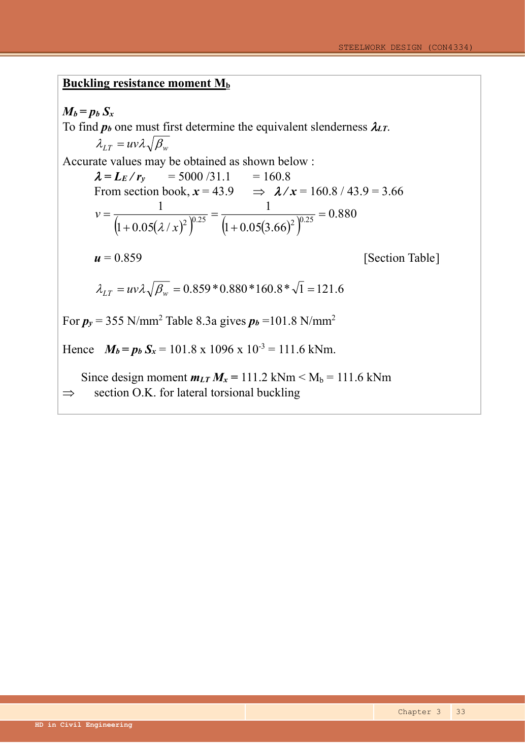
7. Effective length and equivalent slenderness
Simple explanation: Which length belongs in the calculation?
A sideways tie can shorten the buckling region without shortening the beam’s vertical span.
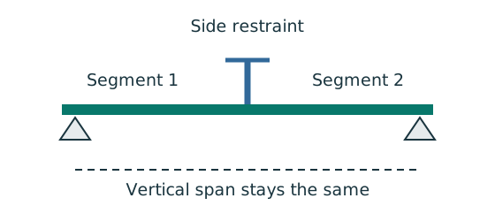
- Separate vertical-support spacing from lateral-restraint spacing.
- Apply the course rule for the actual end restraint and loading.
- Keep the original vertical load analysis unless its supports change.
Remember: Restraints in one direction may not restrain the other direction.
The source rounds to and to , obtaining . Both approaches pass, but the exact values avoid losing the small margin in this example.
Animation labA beam bends sideways and twists
Supplement to the original lesson. Enable JavaScript to play, step through calculations and rotate 3D models. The following explanation remains readable offline.
- For the illustrated sagging beam the top flange is compressed.
- The unrestrained compression flange can move sideways while the complete cross-section twists.
- Only effective restraints divide the member into unbraced segments. They do not automatically add vertical supports.
- Use the segment effective length, section properties and matching moment factor. This is an exaggerated mode shape, not a calculated displacement.
8. Interpolate strength and compare
Simple explanation: A beam can escape sideways
The compressed flange can move sideways while the section twists.
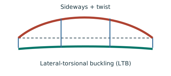
- Divide the beam at effective lateral restraints.
- Use each segment’s effective length to obtain its buckling resistance.
- Compare that resistance with the segment’s equivalent moment demand.
Remember: A section bending check alone does not check lateral-torsional buckling.
The lecturer’s rounded route gives pᵦ=101.8 and Mᵦ=111.6 kNm against , also a pass. Do not claim a large reserve. The illustrated solution checks shear, section bending and LTB; bearing dimensions are absent. The characteristic imposed load arrangement is known, but a finish limit is not specified in this example’s question. Those additional design conditions must be supplied before a blanket full-design conclusion.
Animation labA beam bends sideways and twists
Supplement to the original lesson. Enable JavaScript to play, step through calculations and rotate 3D models. The following explanation remains readable offline.
- For the illustrated sagging beam the top flange is compressed.
- The unrestrained compression flange can move sideways while the complete cross-section twists.
- Only effective restraints divide the member into unbraced segments. They do not automatically add vertical supports.
- Use the segment effective length, section properties and matching moment factor. This is an exaggerated mode shape, not a calculated displacement.
Compact exam answer
Use S355 UB, Class 1. Each ,,,. ,. ; , demand . , , ; interpolate . ; LTB passes by only a small margin.
Mistakes to avoid
- Point-load positions do not imply intermediate restraints.
- Use quarter points , not the load positions .
- Read pᵦ using λᴸᵀ, not .
- Do not round a narrow pass into an unsupported generous margin.
Procedure for an unfamiliar variant
- Identify the vertical supports, span, lateral restraints and individual load positions.
- Keep dead and imposed loads separate; form the required ultimate and serviceability cases.
- Find reactions and the maximum shear/moment by equilibrium, with units.
- Choose a section-table row, confirm thickness-dependent strength, and classify both flange and web.
- Check shear and bending; add segment LTB where restraint is discrete.
- Complete the requested web and deflection checks; state the governing result and any missing data.
Independent self-check
Try it yourself. Invented variant: all ultimate loads increase by , with geometry and section unchanged. Does the LTB check still pass?
Reveal answer and reasoning
The moment shape and mᴸᵀ stay unchanged; resistance stays . Demand becomes , exceeding resistance. The beam fails LTB even though section bending and shear have ample reserve.
Animation labRead the moment shape within one segment
Supplement to the original lesson. Enable JavaScript to play, step through calculations and rotate 3D models. The following explanation remains readable offline.
- Moment ordinates must belong to the same effective unbraced segment.
- Same-side and reverse-curvature diagrams have different signed end ratios.
- The markers show ¼, ½ and ¾ of this segment, not of the entire beam.
- LTB and column flexural factors are different. Preserve their individual bounds and coefficient sets.