Beam example 2: trace a library-floor load into beam B3
Open “Animation lab” beside a teaching step for a visual explanation or a walkthrough of its original expressions. Models are illustrative; source answers remain unchanged.
← Read this lecture example beside its chapter concepts
Need a simpler picture? Open “Simple explanation” beside a difficult step. These optional notes do not replace the full solution.
Design the fully restrained supporting beam B3 in the library floor plan. Characteristic dead and imposed floor loads are and ; the dead load includes the self-weight allowances used by the example. Use S355 and the lecturer’s simply supported member model.
Original source: LectureNotes/Ch 3_Beam.pdf — p. 22, p. 23, p. 24, p. 25, p. 26. Values tagged given are in the question or diagram; lookup values come from a named table; calculated values follow from the working; assumptions are stated explicitly.
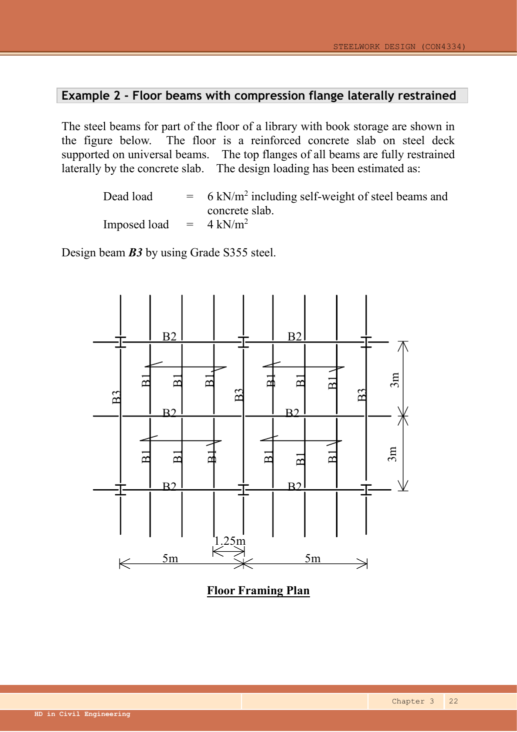
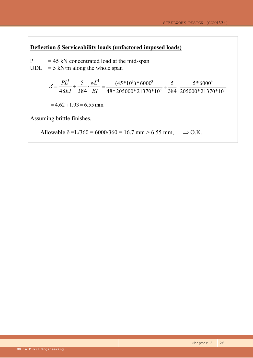
Read the diagram and collect the data
| Feature | Meaning for loading |
|---|---|
| Slab span marks crossing the B1 lines | Slab load reaches the parallel B1 beams over a tributary width. |
| B1 above and below each interior B2 | Each B2 loading point receives two B1 end reactions. |
| B2 on both sides of the interior B3 | B3 receives two B2 end reactions at its centre. |
| B3 also directly borders slab strips | Interior B3 carries its own tributary slab strip, represented as a UDL. |
| Given and assumed | All self-weight is already allowed for in the supplied dead intensity. B3 fully restrained; lecturer assumes brittle finishes for serviceability. |
Before calculating: recognition and strategy
Work upstream before downstream: slab → B1 → B2 → B3. A supporting beam receives a point load equal to the end reaction of the supported beam, not that beam’s entire load. Keep dead and imposed reactions separate until the B3 loading is established. Do not treat the horizontal bay width as the B3 span.
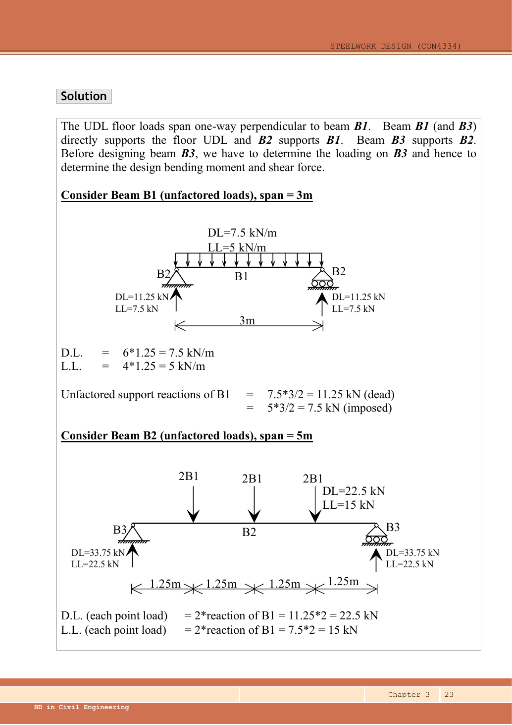
1. Slab to B1
The division by two comes from a uniformly loaded simply supported span. These are characteristic reactions, before the ultimate factors.
Animation labFollow the floor load in 3D
Supplement to the original lesson. Enable JavaScript to play, step through calculations and rotate 3D models. The following explanation remains readable offline.
- The floor carries pressure in . The highlighted strip belongs to one secondary beam.
- Multiply pressure by tributary width: . The illustration uses .
- A primary beam receives the secondary beam reaction at their connection, not a new full-span UDL.
- Trace reactions down to columns and foundations. Count each loaded area once.
2. B1 reactions to B2
There are three internal point loads, not four: four slab strips are bounded by three interior B1 lines and the two B3 boundaries. Symmetry of the three loads gives half the total at each B2 end. Loads arriving directly at column-supported beam ends do not add span bending.
Animation labFollow the floor load in 3D
Supplement to the original lesson. Enable JavaScript to play, step through calculations and rotate 3D models. The following explanation remains readable offline.
- The floor carries pressure in . The highlighted strip belongs to one secondary beam.
- Multiply pressure by tributary width: . The illustration uses .
- A primary beam receives the secondary beam reaction at their connection, not a new full-span UDL.
- Trace reactions down to columns and foundations. Count each loaded area once.
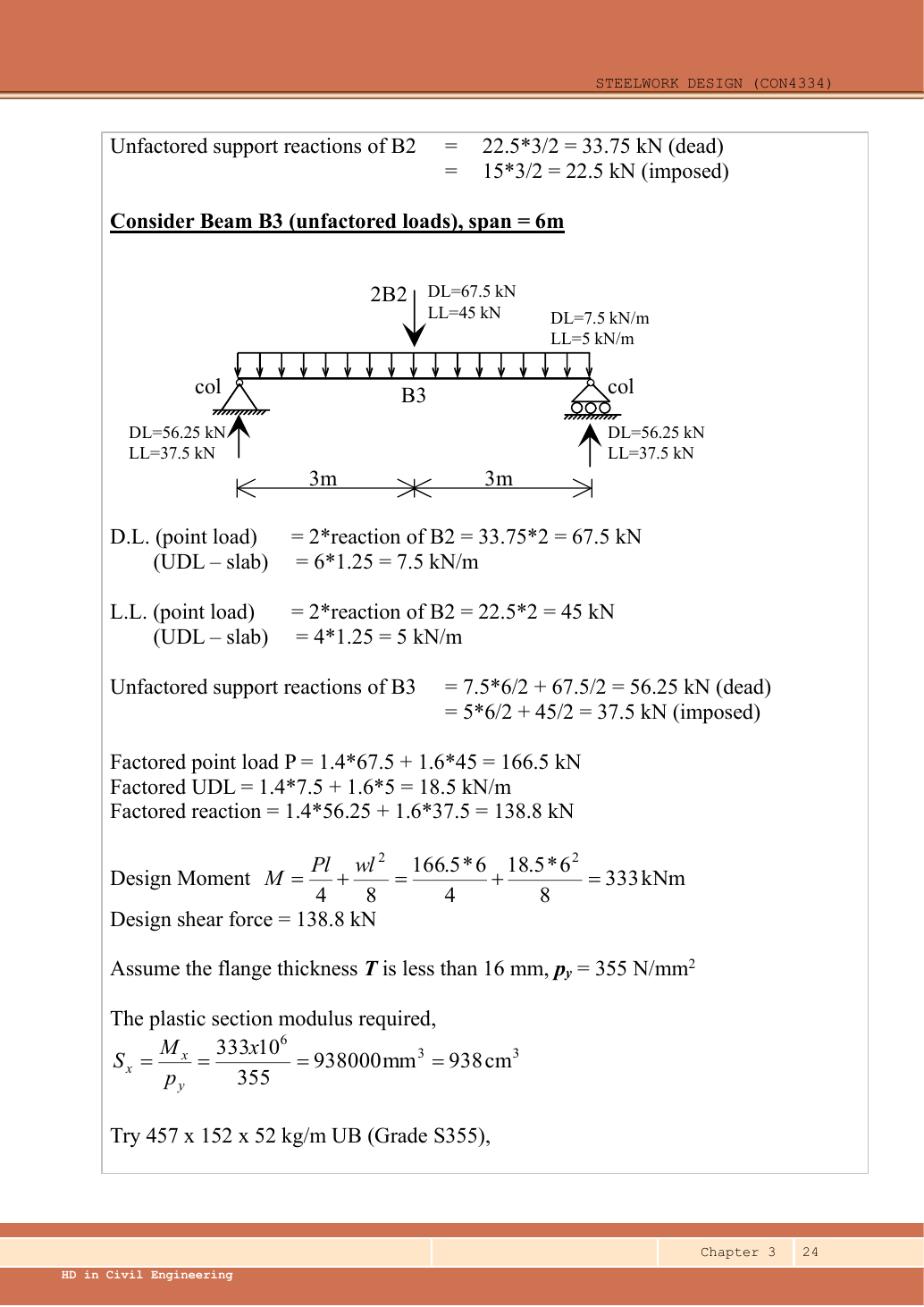
3. Assemble B3 point load and direct slab UDL
Simple explanation: How a floor load reaches a beam
Each beam collects the load from its own strip of floor.
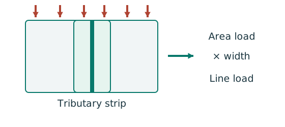
- Find the tributary width from the actual plan.
- Area load × tributary width gives load per beam length.
- A supporting beam receives the other beam’s end reaction.
Remember: A reaction becomes a point load, not automatically a UDL.
The factor of two at the central point represents the B2 on each side of B3. It does not double B3’s span or its tributary strip.
Animation labFollow the floor load in 3D
Supplement to the original lesson. Enable JavaScript to play, step through calculations and rotate 3D models. The following explanation remains readable offline.
- The floor carries pressure in . The highlighted strip belongs to one secondary beam.
- Multiply pressure by tributary width: . The illustration uses .
- A primary beam receives the secondary beam reaction at their connection, not a new full-span UDL.
- Trace reactions down to columns and foundations. Count each loaded area once.
4. Reactions, shear and moment of B3
Simple explanation: Why reactions balance the loads
Think of a seesaw that must neither fall nor turn.
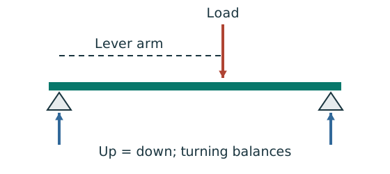
- Upward and downward forces must balance.
- Take moments about a support to eliminate its reaction.
- Use perpendicular distance from the point to the force line.
Remember: A lateral restraint is not automatically a vertical support.
Animation labBalance reactions and moments
Supplement to the original lesson. Enable JavaScript to play, step through calculations and rotate 3D models. The following explanation remains readable offline.
- This demonstrator is a simply supported 6 m beam with a 60 kN point load; it is not the page’s original loading diagram.
- . Moving the load towards B increases .
- . The two upward reactions must sum to P.
- With the load at midspan, . End couples, UDLs and overhangs require their own equilibrium terms.
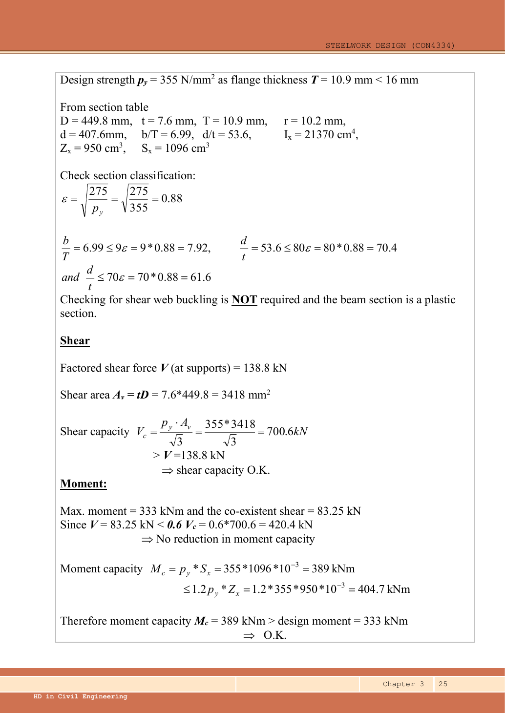
5. Select UB
Data File p.9 row gives , , , , , and . Page 10, the same designation, gives , , . confirms pᵧ=355. No interpolation is used for section properties: read the exact row.
Animation labRead a table without losing the keys
Supplement to the original lesson. Enable JavaScript to play, step through calculations and rotate 3D models. The following explanation remains readable offline.
- Name the required property: material strength, section property, buckling strength or a moment factor.
- Keep section size, steel grade, thickness band, curve and axis as separate lookup keys.
- , and require different conversion powers. Do not use adjacent columns interchangeably.
- Use bracketing rows within the same valid column. The original page remains the source of all table values.
6. Classify the trial section
Animation labWhy thin elements buckle locally
Supplement to the original lesson. Enable JavaScript to play, step through calculations and rotate 3D models. The following explanation remains readable offline.
- The flange outstand and web have different widths, thicknesses and edge support conditions.
- A thinner plate can wrinkle locally before the complete member loses stability.
- Class 1 allows plastic rotation; Class 2 reaches plastic resistance; Class 3 reaches elastic resistance; Class 4 requires effective properties.
- Check every relevant compression element with the supplied limits and stress distribution. The deformation shown is qualitative.
7. Check shear resistance
Animation labSee shear in the web
Supplement to the original lesson. Enable JavaScript to play, step through calculations and rotate 3D models. The following explanation remains readable offline.
- Internal shear keeps the two sides of the cut in vertical equilibrium.
- For the course’s common I-section case, the web provides the principal shear area; use the specified definition.
- A slender web may require a different shear-buckling route before a simple shear-resistance formula is used.
- Use where applicable in the course. Convert N to kN before comparing with design shear.
8. Check moment resistance
Simple explanation: Why one flange squeezes and the other stretches
Bending makes opposite sides of the section do opposite jobs.
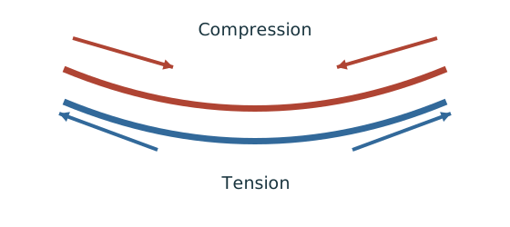
- Find the moment from the actual loads and supports.
- Choose the resistance formula allowed by the section class.
- Check whether the coexistent shear changes that formula.
Remember: Use shear at the location being checked, not an unrelated maximum.
The source’s requested B3 design demonstrates shear, moment and deflection. It does not specify a bearing geometry for a numerical local-web design here. Do not import the bearing from Example 1.
Animation labCompression and tension across a section
Supplement to the original lesson. Enable JavaScript to play, step through calculations and rotate 3D models. The following explanation remains readable offline.
- For sagging, the top flange is in compression and the bottom in tension; hogging reverses this.
- Elastic bending stress varies with distance from the neutral axis: .
- The section class governs whether elastic, plastic or effective properties may be used.
- Use the shear at the section under examination; the largest shear elsewhere is not automatically coexistent.
9. Check B3 serviceability
Simple explanation: How much does the beam sag?
Strength asks whether it fails; deflection asks how far it moves.
- Use the serviceability load case specified by the course question.
- Choose the expression matching the support and load positions.
- Use consistent units for load, length, E and I.
Remember: The largest deflection is not always at midspan.
Animation labSee stiffness and deflection
Supplement to the original lesson. Enable JavaScript to play, step through calculations and rotate 3D models. The following explanation remains readable offline.
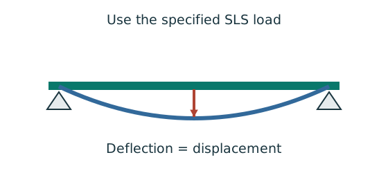
- Use the specified SLS load, span and support arrangement. The demonstrator has a full-span UDL.
- The loaded beam bends; the deformation is exaggerated so its shape can be seen.
- For a simply supported full-span UDL, . Double L with w, E and I unchanged: δ becomes 16 times as large.
- The readout uses , and . Select the finish/support-specific limit from the original table.
Compact exam answer
B1 characteristic reactions /=/. B2 has three / points; end reactions /. B3 central /=/ plus /. Ultimate , , , . Select UB S355, Class 1: , , . The demonstrated checks pass.
Mistakes to avoid
- Do not make floor pressure a beam UDL without multiplying by tributary width.
- Do not transfer a supported beam’s entire load to each end.
- Include B3’s directly supported slab strip once.
- Do not add self-weight already included by the problem.
Procedure for an unfamiliar variant
- Identify the vertical supports, span, lateral restraints and individual load positions.
- Keep dead and imposed loads separate; form the required ultimate and serviceability cases.
- Find reactions and the maximum shear/moment by equilibrium, with units.
- Choose a section-table row, confirm thickness-dependent strength, and classify both flange and web.
- Check shear and bending; add segment LTB where restraint is discrete.
- Complete the requested web and deflection checks; state the governing result and any missing data.
Independent self-check
Try it yourself. Invented variant: only the characteristic floor imposed pressure rises from to . Find the revised B3 ultimate and , and imposed deflection; retain the original dead loading.
Reveal answer and reasoning
All imposed effects multiply by . B3 imposed point; imposed UDL. ; . . Imposed deflection=. Maximum shear=; these checks still pass.
Animation labFollow the floor load in 3D
Supplement to the original lesson. Enable JavaScript to play, step through calculations and rotate 3D models. The following explanation remains readable offline.
- The floor carries pressure in . The highlighted strip belongs to one secondary beam.
- Multiply pressure by tributary width: . The illustration uses .
- A primary beam receives the secondary beam reaction at their connection, not a new full-span UDL.
- Trace reactions down to columns and foundations. Count each loaded area once.