Connection example 2: design a bolted tension splice
Open “Animation lab” beside a teaching step for a visual explanation or a walkthrough of its original expressions. Models are illustrative; source answers remain unchanged.
← Read this lecture example beside its chapter concepts
Need a simpler picture? Open “Simple explanation” beside a difficult step. These optional notes do not replace the full solution.
Design a double-cover splice for an already ultimate tensile force of . Main plates are wide × thick; two S355 cover plates are thick. Use Grade 8.8 M20 bolts in holes, pitch and end distance.
Original source: LectureNotes/Ch 2_Connection.pdf — p. 18, p. 19, p. 20. Values tagged given are in the question or diagram; lookup values come from a named table; calculated values follow from the working; assumptions are stated explicitly.
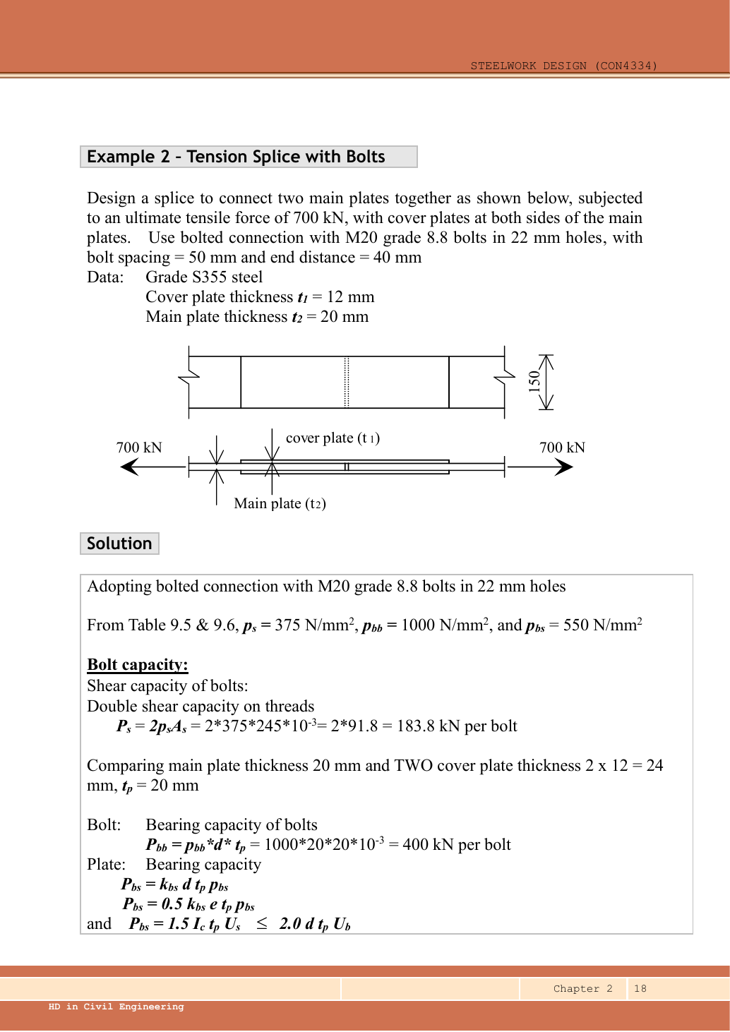
Read the diagram and collect the data
| Input | Origin |
|---|---|
| Given demand | ultimate; no further factor. |
| Given thicknesses | Main ; each cover ; cross-section view labels each ply. |
| Given hole/pitch/end | M20 → ; stated hole ; longitudinal pitch ; end . |
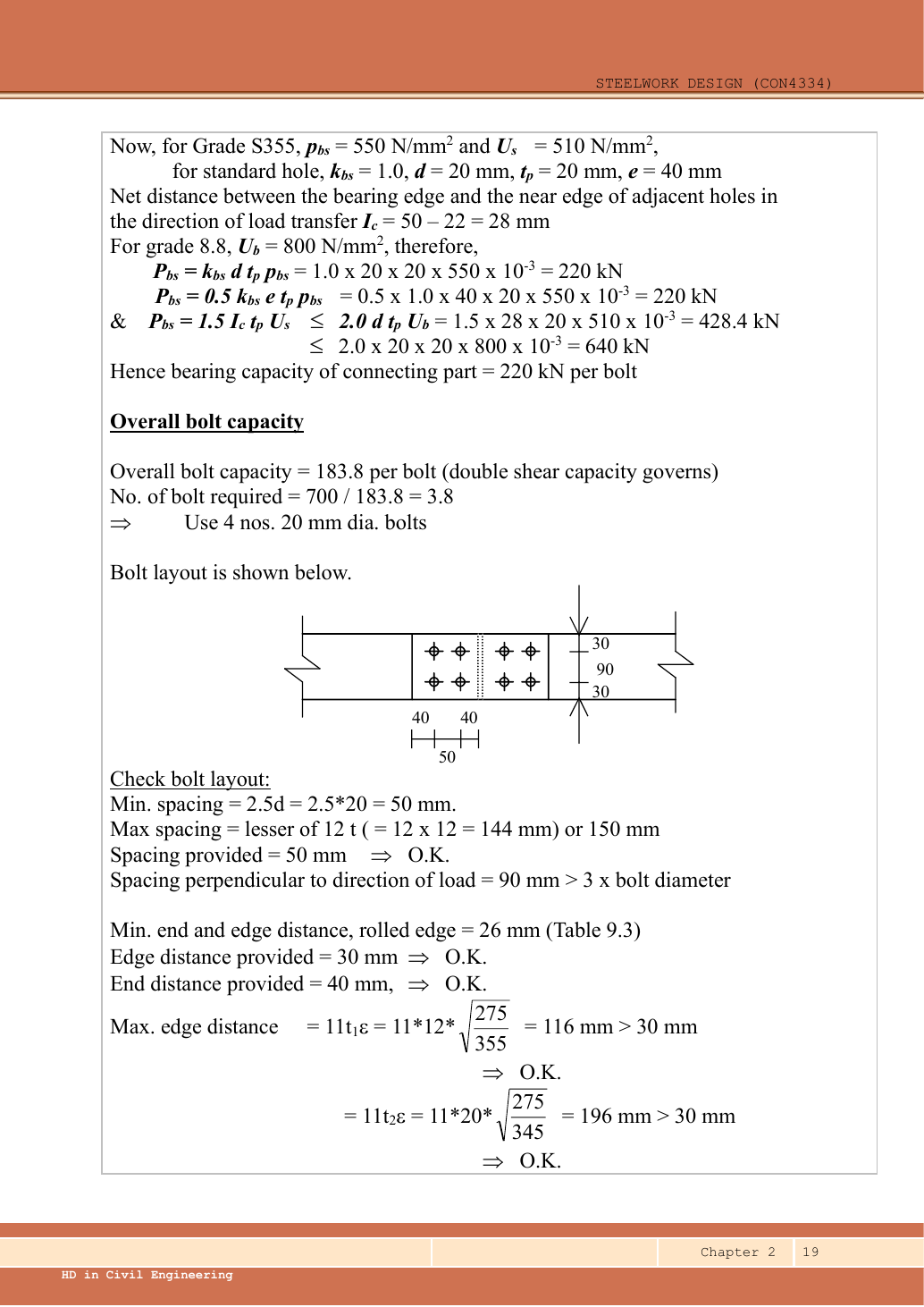
| Selected layout | p.19 drawing: two rows, gauge , side edges , two columns per half-splice. |
| Lookup | , , ; S355 , , . Main for ; covers for . All stress units . |
Before calculating: recognition and strategy
Each half-splice must transfer the full from a main plate into the covers. The covers each take half that force. Bolts have two shear planes; compare main thickness with total cover thickness for the bearing path. Select bolt count from the weakest per-bolt mode, round up, arrange the bolts, then check the plates cut by those holes.
1. Establish the capacity of one bolt and its bearing path
Simple explanation: Count where the bolt can be sheared
The plate interfaces are the places trying to cut across the bolt.
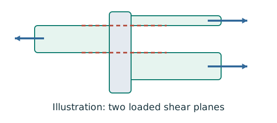
- Count actual loaded shear planes, not merely visible plates.
- Choose shank or threaded area for the plane concerned.
- Compare group resistance with the force that group transfers.
Remember: Bolts on opposite sides of a splice do not all act in parallel.
Using total cover thickness is valid here because the two identical covers share the force symmetrically. An unequal cover arrangement would need separate load-sharing checks.
Animation labCount the bolt shear planes
Supplement to the original lesson. Enable JavaScript to play, step through calculations and rotate 3D models. The following explanation remains readable offline.
- Load must cross an interface between the connected plates.
- A lap joint gives one shear plane through a bolt.
- A symmetric double-cover joint may provide two shear planes. Count load-transfer interfaces, not just visible plates.
- Use the source’s area and shear strength. Then check bearing, plate resistance and detailing separately.
2. Select bolts on each side of the splice
Provide four on the left and four on the right: eight physical bolts in total. The eight do not jointly give “” across the splice, because the left and right groups carry the same force in series.
Animation labCount the bolt shear planes
Supplement to the original lesson. Enable JavaScript to play, step through calculations and rotate 3D models. The following explanation remains readable offline.
- Load must cross an interface between the connected plates.
- A lap joint gives one shear plane through a bolt.
- A symmetric double-cover joint may provide two shear planes. Count load-transfer interfaces, not just visible plates.
- Use the source’s area and shear strength. Then check bearing, plate resistance and detailing separately.
3. Verify the selected layout
The two transverse rows are separated by . Width closure:. Longitudinal pitch and end are the specified values. Use the source’s rolled-edge condition in Table 9.3, M20 row: minimum .
Animation labBolt centres, holes and edges
Supplement to the original lesson. Enable JavaScript to play, step through calculations and rotate 3D models. The following explanation remains readable offline.
- Hole diameter d₀ differs from nominal bolt diameter d. Net-section deductions use the specified hole.
- Pitch runs along the load direction; gauge measures spacing across rows.
- End and edge distances start at the hole centre. The remaining ligament starts at the hole boundary.
- Minimum spacing, edge distances, grip and plate thickness come from the specified rules, not this scaled illustration.
4. Check main-plate tension across two holes
Simple explanation: Why holes reduce tension resistance
The pull must squeeze through the steel left beside the holes.
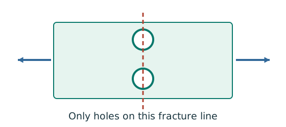
- Choose a possible fracture line across the member.
- Subtract the holes crossed by that line using hole diameter.
- Apply the course effective-area rule and its gross-area limit.
Remember: Do not subtract every hole anywhere in the connection.
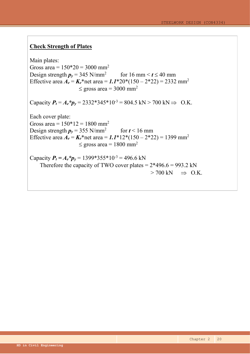
The critical straight transverse line crosses one hole in each row: two holes. Do not deduct all four holes along a half-splice. Thickness selects .
Animation labSubtract holes on the failure path
Supplement to the original lesson. Enable JavaScript to play, step through calculations and rotate 3D models. The following explanation remains readable offline.
- Gross area counts the complete plate width and thickness.
- The highlighted transverse path passes through the bolt holes.
- For the straight illustrative path, . Staggered paths require their specified correction.
- Net area is not always effective area. Include the course’s strength ratio or shear-lag rule when applicable.
5. Check both covers and conclude
All requested checks pass under the stated rolled-edge layout. The least load-path resistance is bolt shear . The source gives approximately for covers after intermediate rounding; carrying full precision gives .
Animation labSubtract holes on the failure path
Supplement to the original lesson. Enable JavaScript to play, step through calculations and rotate 3D models. The following explanation remains readable offline.
- Gross area counts the complete plate width and thickness.
- The highlighted transverse path passes through the bolt holes.
- For the straight illustrative path, . Staggered paths require their specified correction.
- Net area is not always effective area. Include the course’s strength ratio or shear-lag rule when applicable.
Compact exam answer
Four M20 Grade 8.8 bolts per side (eight total), two rows with gauge, pitch, ends and rolled edges. Double-shear resistance per half; bearing exceeds this. Main tension ; combined cover tension . Each exceeds . Layout passes for the source’s rolled-edge assumption.
Mistakes to avoid
- Do not factor the already ultimate .
- Four bolts are required on each side of the plate butt.
- Double shear doubles bolt shear, not the main-plate thickness.
- A transverse net section crosses two holes, not four.
Procedure for an unfamiliar variant
- Trace one half-splice at full force and each cover at its share.
- Calculate per-bolt shear/bearing and take the minimum.
- Round up bolt count and draw a feasible layout.
- Check every pitch/edge rule using the thinner ply and correct edge finish.
- Check main and cover effective tension areas independently.
Independent self-check
Try it yourself. If the required ultimate force becomes but the splice is unchanged, which calculated resistance fails first?
Hint
Compare with the complete group resistance, not just one bolt.
Reveal answer and reasoning
Bolt shear is inadequate. Main-plate tension and cover-pair tension still exceed . Adding bolts changes the layout and may change the fracture path, so repeat layout/net-area checks.