Assignment 2 Q3: classification, protection, built-up sections and second-order analysis
Open “Animation lab” beside a teaching step for a visual explanation or a walkthrough of its original expressions. Models are illustrative; source answers remain unchanged.
Need a simpler picture? Open “Simple explanation” beside a difficult step. These optional notes do not replace the full solution.
Answer all four theory parts: describe the four section classes; sketch two UB fire-protection methods; identify two built-up sections with sketches; and explain the HK2011 second-order elastic / method with a sketch.
Original source: Assignment/AY2627s 1-CON4334-Assignment 2.pdf — p. 2. Values tagged given are in the question or diagram; lookup values come from a named table; calculated values follow from the working; assumptions are stated explicitly.
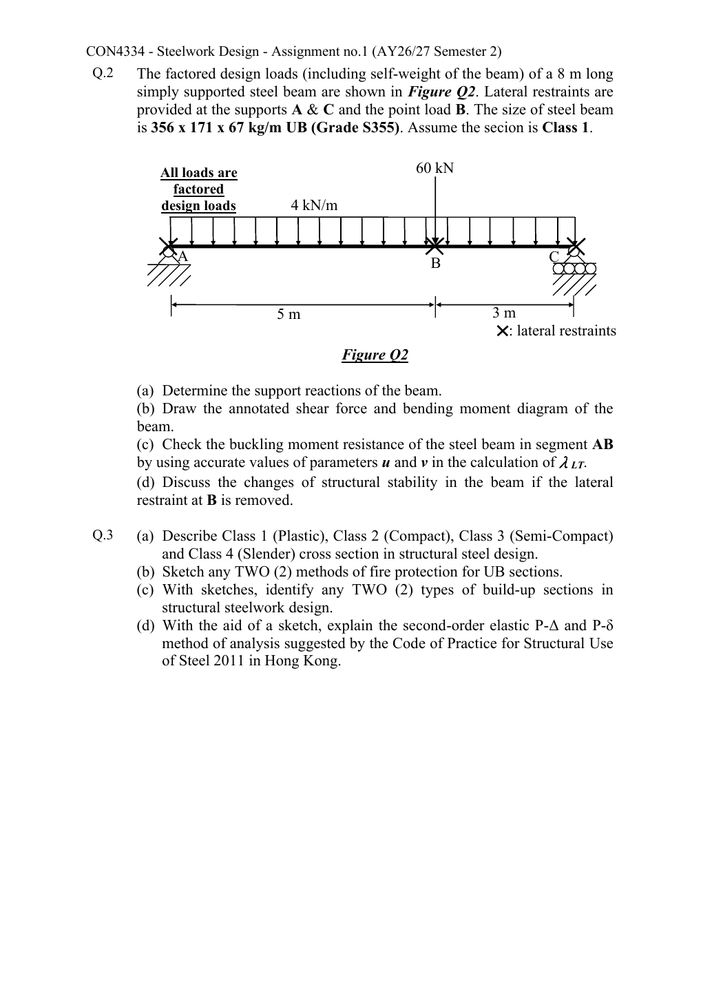
Read the diagram and collect the data
Given scope: the four requested theory topics and the HK Steel Code 2011 course basis. There are no design temperatures, fire durations, loads, stiffnesses or numerical displacements to calculate. The answer should identify mechanisms and label sketches without inventing product thicknesses or ratings.
Before calculating: recognition and strategy
For a theory answer, pair each term with its physical mechanism and design consequence. Sketches should make the distinguishing feature visible: rotation ability for classes, a protection barrier around the steel, component plates in a built-up section, and two different deflections for second-order effects. The original fire figure labels are Solid Casing, Hollow Casing and Profile Casing. The board and sprayed examples below are explained material implementations of the hollow/profile shapes; those material labels are teaching annotations, not words printed on the source drawing.
(a) Describe Classes 1–4
Simple explanation: A thin part can wrinkle first
A thin plate may wrinkle before the whole steel member reaches its intended resistance.
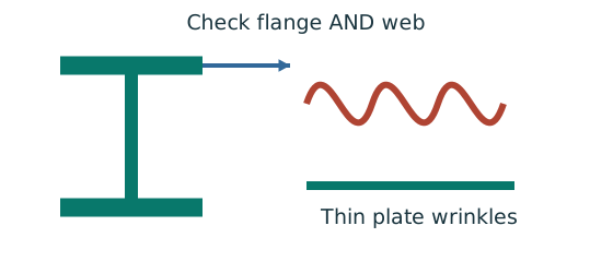
- Check flange and web slenderness using their own definitions.
- Compare each ratio with the correct class limits.
- The less favourable element determines the section class.
Remember: Bending limits and uniform-compression limits are different.
| Class | What happens in bending | Key phrase for an exam answer |
|---|---|---|
| 1 plastic | The section reaches full plastic resistance and can undergo sufficient plastic rotation before local buckling. | Plastic moment and plastic-hinge rotation capacity. |
| 2 compact | The section reaches plastic resistance but has insufficient rotation capacity for a fully developed plastic hinge/redistribution assumption. | Plastic moment, limited rotation. |
| 3 semi-compact | An extreme fibre reaches yield; local buckling prevents full plastic stress redistribution. | Elastic first-yield resistance pᵧZ. |
| 4 slender | Local buckling occurs before gross-section yield resistance is reached. | Effective section/local-buckling treatment needed. |
The least favourable relevant compression element governs the overall class. Classification depends on width/thickness ratio, material strength throughε and stress pattern. It is independent of whether the whole member can undergo lateral-torsional buckling. Classes 1/2 use the course capped plastic expression min(pᵧS,1.2pᵧZ); do not erase the ceiling.
Animation labWhy thin elements buckle locally
Supplement to the original lesson. Enable JavaScript to play, step through calculations and rotate 3D models. The following explanation remains readable offline.
- The flange outstand and web have different widths, thicknesses and edge support conditions.
- A thinner plate can wrinkle locally before the complete member loses stability.
- Class 1 allows plastic rotation; Class 2 reaches plastic resistance; Class 3 reaches elastic resistance; Class 4 requires effective properties.
- Check every relevant compression element with the supplied limits and stress distribution. The deformation shown is qualitative.
(b) Sketch two fire-protection methods
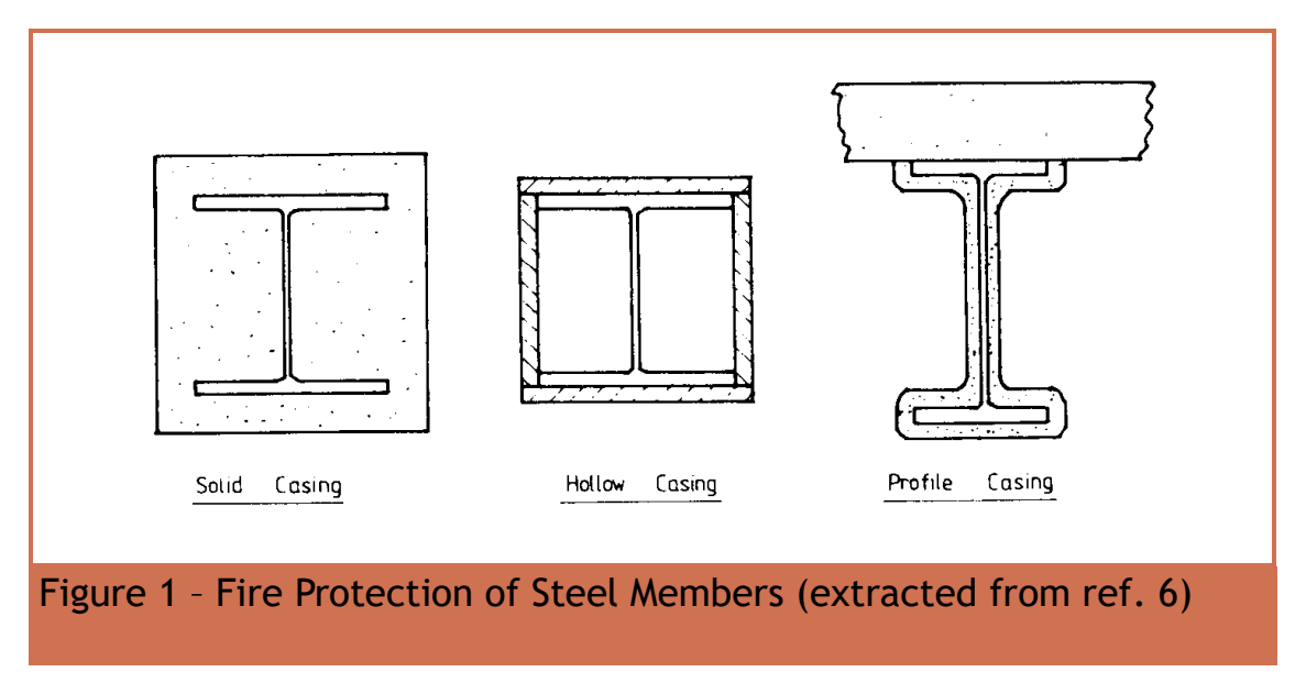
| Method to sketch | Labels and explanation |
|---|---|
| Board encasement | Draw the steel I section inside a rectangular board casing. Label UB, fire-resistant boards, board joints/fixings and the enclosed space. The casing delays heat reaching the steel. |
| Sprayed protection | Draw a layer following the exposed I-profile: flange tops/undersides, web faces and flange edges. Label UB and sprayed insulating fire-protection layer. It delays the steel temperature rise over exposed surfaces. |
Explain why protection is needed: elevated temperature reduces steel strength and stiffness, so a normally adequate member may lose load resistance or stability. A sketch of an unlabelled rectangle alone does not distinguish a board system from concrete encasement. No required rating, tested system or thickness is supplied; do not assign a fictitious coating thickness or “two-hour” rating.
Animation labSee the fire-protection enclosure
Supplement to the original lesson. Enable JavaScript to play, step through calculations and rotate 3D models. The following explanation remains readable offline.
- Steel loses strength as it heats. Protection aims to delay heat reaching the section.
- Solid casing fills the enclosure around the I-section.
- A hollow enclosure surrounds the section while leaving an air space.
- Profile casing follows the section outline. The supplied sketch does not determine protection thickness or fire duration.
(c) Sketch and identify two built-up sections
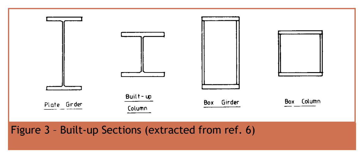
| Section | What the sketch must show |
|---|---|
| Welded I section / plate girder | One vertical web plate between two horizontal flange plates. Mark longitudinal welds joining the web to each flange. Label each plate separately; the assembled I is not a single hot-rolled product. |
| Welded box section | Four plate walls forming a closed rectangle, with corner longitudinal welds. Label top/bottom flange plates and the two side webs; show the hollow interior. |
A built-up section is fabricated by joining components to obtain a required form or size. In the I section, flanges principally provide bending resistance and the web mainly carries shear; in the box, the closed shape also supplies torsional stiffness. These are qualitative functions, not a substitute for strength/buckling checks. A hot-rolled UB drawn without component boundaries or welds does not illustrate a built-up section.
Animation labExplore section geometry and axes
Supplement to the original lesson. Enable JavaScript to play, step through calculations and rotate 3D models. The following explanation remains readable offline.
- The flanges are the wide plates; the web connects them. Rotate the I-section to see both.
- The same section has different stiffness and resistance about its two principal axes.
- I controls elastic curvature; is elastic section modulus. Plastic modulus S comes from plastic stress blocks.
- Nominal section labels are not every actual dimension. Keep the row, axis and units together.
(d) Second-order elastic and analysis
Simple explanation: Moving sideways gives the load a new lever arm
Once a compressed member moves sideways, the same compression creates extra moment.
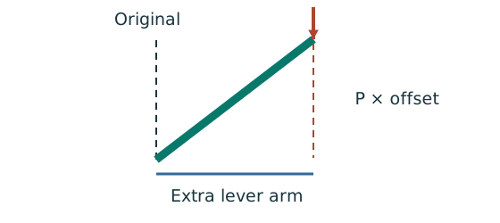
- P–Δ concerns overall frame or storey movement.
- P–δ concerns bowing relative to the member’s end line.
- Amplify only the first-order moments specified by the method.
Remember: Do not amplify a moment that the question already gives as amplified.
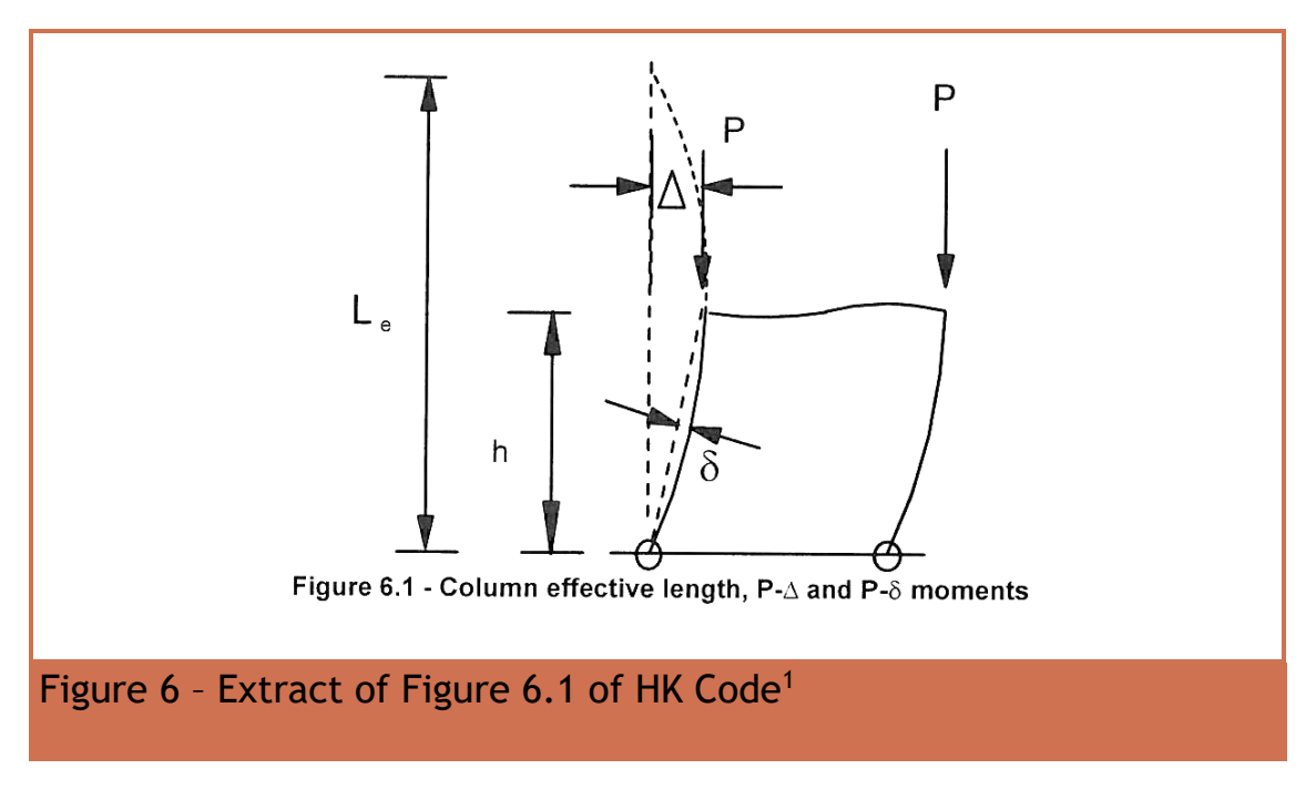
Draw the original straight frame in a light line and the displaced frame in a stronger line. Mark a compression loadP at the top, global horizontal storey displacementΔ and local bowδ relative to the displaced member chord. andδ are lengths, not angles or two names for the same movement.
- Apply the specified loads to an elastic structural model with the relevant initial frame/member imperfections.
- Recognise that equilibrium must be satisfied on the displaced geometry: axial forces acting throughΔ andδ create additional moments.
- Include global sway and local member-curvature effects by second-order analysis, or the course’s permitted equivalent amplification approach within its applicable frame classification.
- Recheck member strength and stability using the resulting design actions; “elastic” describes the material analysis, not a promise that geometry effects are negligible.
The course distinguishes non-sway, sway and ultra-sensitive frames using elastic critical-load sensitivity. An ultra-sensitive frame cannot be justified by simply omitting second-order terms. In a non-sway course example, a local amplification may still be required even when global sway effects are treated as negligible.
Try it yourself.Invented numerical example: , global , local . What additional moment does each produce?
Reveal answer and reasoning
Convert to metres: and . ; . Do not add them blindly at every section: their locations, directions and the analysis model determine how they contribute.
Animation labSeparate P–Δ from P–δ
Supplement to the original lesson. Enable JavaScript to play, step through calculations and rotate 3D models. The following explanation remains readable offline.
- The dashed line marks the original frame position; axial compression acts downwards.
- Global displacement Δ creates the additional moment PΔ.
- Local displacement δ is measured from the line joining the displaced ends, and adds Pδ.
- Follow the original analysis route. Do not amplify an already amplified moment or confuse critical-load factor with member slenderness.
Animation labSeparate P–Δ from P–δ
Supplement to the original lesson. Enable JavaScript to play, step through calculations and rotate 3D models. The following explanation remains readable offline.
- The dashed line marks the original frame position; axial compression acts downwards.
- Global displacement Δ creates the additional moment PΔ.
- Local displacement δ is measured from the line joining the displaced ends, and adds Pδ.
- Follow the original analysis route. Do not amplify an already amplified moment or confuse critical-load factor with member slenderness.
Compact exam answer
(a) Class 1: plastic moment plus rotation; Class 2: plastic moment with limited rotation; Class 3: elastic yield; Class 4: local buckling before gross yield. (b) Draw/label board encasement and profile-following sprayed protection. (c) Draw/label welded plate-girder I and welded four-plate box, including welds. (d) Sketch globalΔ and localδ; second-order elastic analysis satisfies equilibrium on displaced geometry and includes axial-load additional momentsPΔ/ with relevant imperfections.
Mistakes to avoid
- Do not swap Class 2 and Class 3 resistance descriptions.
- Do not invent a protection thickness or fire rating.
- Do not call an ordinary hot-rolled UB a built-up plate girder.
- Do not confuse material nonlinearity with geometric second-order effects.
Procedure for an unfamiliar variant
- Identify the term and give its physical meaning.
- Draw the minimum sketch features that distinguish it.
- Label components, axes or displacements.
- State its consequence for resistance/analysis.
- Avoid adding numerical design claims without source inputs.
Independent self-check
Try it yourself. Invented transfer question: a braced frame has almost zero storey sway but a visibly bowed compression member. Can both second-order effects be dismissed?
Reveal answer and reasoning
No. Small globalΔ does not prove localδ is negligible. Compression acting through the member bow can create local moments. Follow the course’s non-sway member amplification or appropriate second-order procedure.