2022–2024 · Exam-focused route
Recent-paper transfer practice and timed revision
These short questions are invented transfer checks, not predicted exam questions or official marking guidance.
Try each without its answer, say which model applies, then calculate.
Every new worked page also has a separate changed-input self-check.
1. Floor transfer
Keep load categories separate
A floor carries permanent material and changing occupancy loads. Find the design load for the stated check.
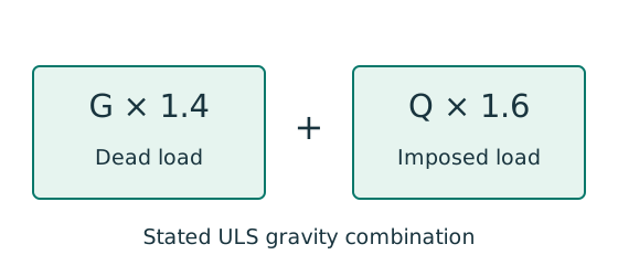
Prediction, then explanation. Increasing imposed load changes its own term. It does not change the dead-load factor or the steel stiffness.
First convert mass to weight where required. Next collect G and Q in compatible units. Apply the combination specified by the course problem.
G is characteristic dead load; Q is characteristic imposed load. Wu is the design load for this course gravity combination.
Scope. This combination is not universal. Use the specified service load for deflection and the stated factors for other standards or cases.
Check and takeaway. Illustration: G = 10 kN and Q = 5 kN give 22 kN. Factoring their sum by one guessed factor loses the distinction.
Balance the isolated beam
Find the two vertical reactions before calculating internal shear or moment.
Prediction, then explanation. Move the same load toward B. Reaction B increases because the load has a larger moment arm about A.
Take moments about A. Reaction A has zero lever arm there. Then use vertical force balance to find reaction A.
P, RA and RB are forces in kN. L is support spacing and a is load position, both in m.
Scope. These expressions describe one point load on a simply supported beam. Add other loads through equilibrium; keep their actual positions.
Check and takeaway. Illustration: P = 60 kN, L = 6 m and a = 2 m give RB = 20 kN and RA = 40 kN.
Apply the reasoning to this section’s data and conditions
Two identical 8 m beams each carry an already-factored UDL of 40 kN/m and meet at the midpoint of a 6 m supporting beam.
Ignore its self-weight.
Find its point load, support shear and maximum moment.
Reveal worked answer
2. Deflection scaling
A safe beam can still sag too far
Check whether the beam displacement exceeds the permitted service limit.
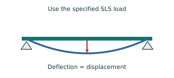
Prediction, then explanation. For the same UDL and stiffness, doubling span multiplies deflection by sixteen. Doubling I halves deflection.
Load bends each beam segment. The curvature accumulates along the span. Material stiffness E and geometric stiffness I resist that deformation.
Use w in N/mm, L in mm, E in N/mm² and I in mm⁴. The resulting midspan deflection is in mm.
Scope. The formula assumes a prismatic, simply supported, linear-elastic beam with full-span UDL. Use the stated service load and deflection limit.
Check and takeaway. A higher yield grade does not automatically increase E. Passing a strength check therefore does not prove acceptable deflection.
Apply the reasoning to this section’s data and conditions
A UDL beam has 12 mm imposed-load deflection.
Increase span by 10%, with the same section and line load.
Estimate the new deflection before recalculating the limit.
Reveal worked answer
The span/360 limit rises only by 10%; utilization rises by 1.1³ = 1.331.
A longer span can lose its margin rapidly.
3. Pick the bolt plane count
One connected leg does not load both legs equally
An angle carries tension through only one leg. Determine how much section area the design rule permits.
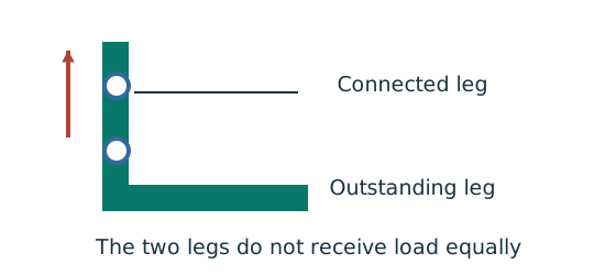
Prediction, then explanation. Keeping the same gross area does not guarantee the same tension resistance when the connection arrangement changes.
Separate connected and outstanding leg areas. Include the actual holes. Then use the supplied single-angle or double-angle effective-area rule.
Ae is the effective area from the applicable angle rule in mm². py is the relevant design strength in N/mm².
Scope. Do not assume the whole gross area is effective. Symmetry, connected leg and connection type determine which rule applies.
Check and takeaway. The outstanding leg contributes through load transfer; the rule need not either count all of it or discard all of it.
The web carries the shear check
Compare the applied shear with the resistance of the prescribed shear area.
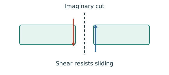
Prediction, then explanation. At fixed design strength and depth, increasing web thickness increases this shear resistance.
Calculate the prescribed shear area. Multiply by the design shear stress from the course rule. Then compare matching force units.
D is overall depth; t is web thickness, in mm. Av uses mm². py uses N/mm², giving Vc in N.
Scope. Apply this area definition to the stated rolled section. Check web slenderness separately. The factor 0.6 is the low-shear threshold, not this resistance coefficient.
Check and takeaway. A shear pass alone does not prove bending, deflection or local support-web adequacy.
Apply the reasoning to this section’s data and conditions
Four M27 Grade 8.8 bolts connect angle–gusset–angle.
Use As=459 mm² and ps=375 N/mm².
What changes if one outer angle is removed and load remains the same?
Reveal worked answer
The shear capacity halves.
Angle tension, eccentricity and bearing also require a new model.
Do not halve only one result and declare the new joint adequate.
4. Choose the weld mechanism
Find which plate buckles first
Before using plastic bending resistance, check whether the flange and web can sustain the required stress distribution.
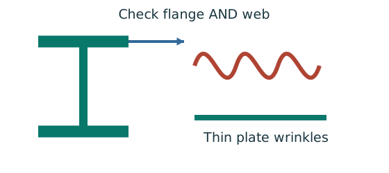
Prediction, then explanation. At fixed width, a thinner plate has a larger width-to-thickness ratio. Local buckling then becomes more restrictive.
Calculate the flange and web ratios separately. Compare each with the limits for its stress condition. The worse class governs.
py is the design yield strength in N/mm². ε is a dimensionless scale used in the supplied classification limits.
Scope. Pure bending and uniform compression use different web limits. Class 2 allows plastic resistance but not the Class 1 rotation capability.
Check and takeaway. A Class 1 web and Class 2 flange give a Class 2 section. Do not average the class numbers.
Treat a weld group as lines
An eccentric force creates direct line force and torsional line force in the same weld group.
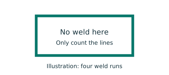
Prediction, then explanation. Increasing eccentricity increases the torsional contribution. The governing corner depends on vector addition, not distance alone.
Find the line centroid. Integrate squared distance along the effective lines. Add direct and torsional components at every candidate critical point.
J is line polar inertia in mm³. x and y use mm. With M in kN·mm, q is line force in kN/mm.
Scope. A solid rectangle has area inertia in mm⁴ and is not this weld-line model. Missing weld sides change the centroid and integrals.
Check and takeaway. Compare the largest resultant line force with the selected throat resistance. Keep kN/mm distinct from total force in kN.
Add force components at each bolt
An in-plane load acts away from the bolt-group centre. Find the largest resultant bolt force.
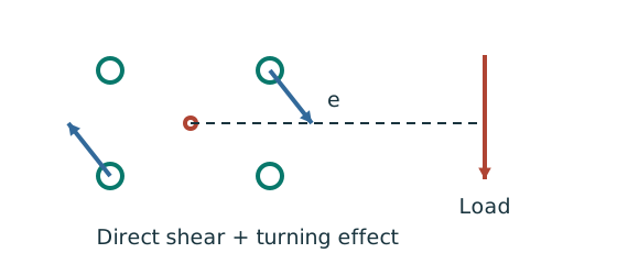
Prediction, then explanation. At fixed force, increasing eccentricity increases the moment component. Its direction differs between bolts.
Locate the bolt-group centre and coordinates. Add horizontal components together and vertical components together before finding each resultant.
e, xi and yi use mm; J uses mm². With M in kN·mm, each moment-force component is in kN.
Scope. These expressions use the stated elastic, equal-bolt in-plane model. Out-of-plane tension and prying require another model.
Check and takeaway. Do not add force magnitudes before resolving directions. Two perpendicular forces of 3 and 4 kN give 5 kN, not 7 kN.
Apply the reasoning to this section’s data and conditions
A load acts in the plane of a closed rectangular weld group, offset from its centroid.
Another bracket assigns shear to web welds and bending to flange welds.
Can their formulas be interchanged?
Reveal worked answer
No. The first needs direct shear plus in-plane torsion using the polar line moment.
The second uses web shear plus an out-of-plane flange force couple with a specified lever arm.
Classify the geometry before selecting an equation.
5. Reversed moments
Moment shape matters within one segment
Represent a nonuniform moment distribution in the applicable member-buckling equation.
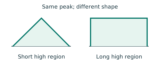
Prediction, then explanation. Two segments can have equal peak moment but different distributions. Their equivalent moment factors can therefore differ.
Evaluate moments from the true whole-beam analysis at the required positions. Apply the exact table’s weights, signs and lower bound.
mLT is an LTB factor. mx and my belong to the specified flexural checks. They are not interchangeable.
Scope. Some rules use magnitudes; others require signed ordinates. A factor does not reduce the actual moment used in a local section check.
Check and takeaway. Measure quarter points from the segment start, not automatically from the beam’s left support.
Apply the reasoning to this section’s data and conditions
Applied top/bottom moments are −80 and +40 kN·m, clockwise positive.
Under the course opposite-end-face convention find the internal ratio and positive-ratio flexural moment factor.
Reveal worked answer
6. Read restraint symbols
Use the same mechanism: Moment shape matters within one segment. Two segments can have equal peak moment but different distributions. Their equivalent moment factors can therefore differ.
Vertical bending can trigger sideways motion
A beam has enough local bending resistance. Check whether its compression flange can move sideways and twist.
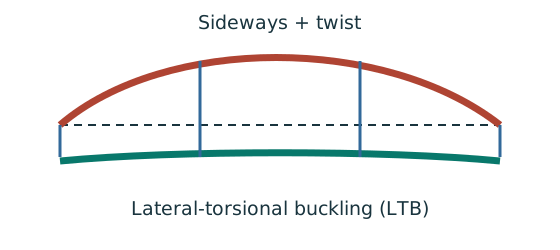
Prediction, then explanation. Adding a valid lateral restraint shortens a stability segment. It need not change the beam’s vertical reaction or moment diagram.
Identify the compressed flange and effective restraints. Calculate the specified slenderness, read buckling strength and compare resistance with the segment demand.
LE and ry use the same length unit. pb uses N/mm²; Sx uses mm³; Mb uses N·mm. mLT is dimensionless.
Scope. Use the specified section class, effective-length branch and loading condition. Load height alone does not prove a destabilizing case.
Check and takeaway. Removing a lateral restraint requires a new segment stability check. The old shorter-segment result cannot establish the longer segment’s adequacy.
Check buckling about both axes
Determine which buckling direction limits the compressed member.
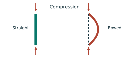
Prediction, then explanation. At fixed radius, longer effective length raises slenderness. The supplied buckling curve generally gives lower compressive strength.
Calculate slenderness about each axis. Select each axis’s curve from section type and thickness. Then obtain and compare the two compressive resistances.
Effective lengths and radii use mm. pc is compressive strength in N/mm²; Ag is gross area in mm²; Pc is in N.
Scope. Do not select the governing axis using radius alone. Effective length and buckling curve can differ. A combined column also needs interaction checks.
Check and takeaway. A short-section yield resistance is not the same as long-member buckling resistance. Keep py and pc distinct.
Apply the reasoning to this section’s data and conditions
A free overhang tip is marked with a lateral-restraint cross.
May you put a vertical reaction there or use the simple-span LTB moment factor?
Reveal worked answer
Neither follows from the cross.
It specifies lateral restraint only.
Solve vertical statics from actual supports.
Apply the cantilever moment-factor and effective-length rules with explicit torsional and loading conditions.
Two-hour recent-paper rehearsal
Change the ruler, keep the quantity
A section table uses centimetres, but the strength calculation uses millimetres. The numbers must describe the same section.
Prediction, then explanation. Would every property increase by ten? No. The exponent determines how many factors of ten are needed.
First identify the physical quantity. Next convert each length factor. Keep force and length conversions separate when converting a moment.
Here n is the length exponent: 2 for area, 3 for section modulus and 4 for second moment of area.
Scope. Changing units changes neither the load nor the section. A conversion factor cannot repair a formula for the wrong physical quantity.
Check and takeaway. Illustration: . The fourth power belongs to the unit, not the number 2.
A table value has conditions
Find a design property without mixing a row, column or standard from a different case.
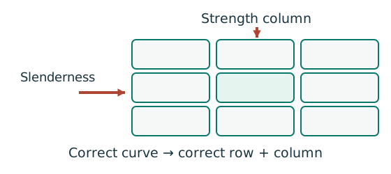
Prediction, then explanation. A different flange thickness can select a lower design strength even when the steel grade name remains unchanged.
Match the complete section designation. Read the relevant axis and unit. For strength tables, select material, thickness and curve before interpolating.
Given values come from the question. Lookup values come from a named table. Assumed values require an explicit condition.
Scope. A missing row or omitted restraint cannot be recovered from a schematic’s scale. Keep the result conditional when required data are absent.
Check and takeaway. Record the table, row, column and unit beside the substitution. That makes a later check possible.
Apply the reasoning to this section’s data and conditions
Use the supplied 2024 paper for a closed-answer first attempt, then the 2023 FT/PTD paper as a transfer attempt.
If you already studied both, use the existing invented two-hour mock and full solutions.
Keep the source data tables available as allowed by the printed paper format.
Use the supplied exam format
Ask two separate design questions
Decide whether the check concerns failure or unacceptable behaviour during use.
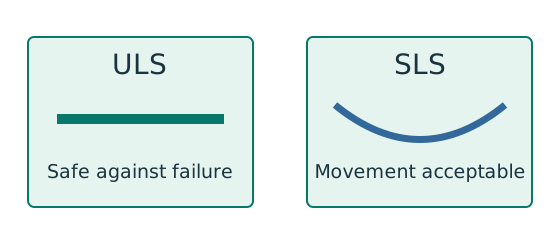
Prediction, then explanation. A larger section may improve both results, but a pass on one branch does not prove a pass on the other.
ULS addresses relevant strength and stability failure modes. SLS addresses specified service conditions such as deflection.
δ is the calculated displacement; δlimit is the permitted displacement. Both must use the same length unit.
Scope. Use each check’s own load combination and limit. A strength load factor does not change the physical stiffness.
Check and takeaway. Write separate conclusions for strength, stability and serviceability where requested. A single unexplained “safe” hides those distinctions.
Apply the reasoning to this section’s data and conditions
Two hours.
Section A is compulsory: 40 marks.
Choose any TWO of the three Section B questions, 30 marks each.
Answer 100 marks out of 130 offered.
These are printed allocations, not an invented marking scheme.
Suggested timing: 5 minutes to read and choose, 42 minutes for Section A.
Allow 32 minutes per chosen Section B question, 9 minutes to check.
Choose using the entire question, including the smaller subparts and missing assumptions.
Record a decision log after the attempt: first wrong step, its source, the corrected method, and a changed-input re-test.
Award yourself no “official method marks”: no marking scheme was supplied.
One suggested readiness check uses the two-hour paper format.
It includes Section A and two Section B families.
A complete answer states units and source assumptions.
Independent completion without consulting solutions is a later practice goal, not a requirement for reading this edition.
Last-pass decision checklist
Compression acts on the displaced shape
A compressed member moves away from its initial load line. Explain why the bending moment can increase.
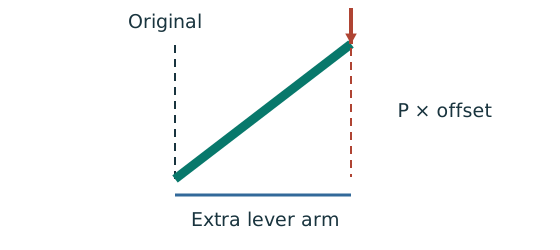
Prediction, then explanation. At fixed axial force, a larger offset creates a larger additional moment. This can further increase the displacement.
Force acting through an offset forms a moment. Second-order analysis includes that changed geometry in equilibrium.
P is axial force. Δ and δ are the relevant perpendicular displacements. Consistent force and length units give moment units.
Scope. Use the amplification or analysis method stated for the frame. Do not amplify an already amplified moment a second time.
Check and takeaway. Zero offset removes this additional moment in the ideal sketch. Real design may still require imperfections and code checks.
Count cuts through each loaded bolt
Find how many shear planes transfer the force through one side of the connection.
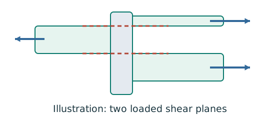
Prediction, then explanation. For equal sharing and unchanged bolt area, two active planes provide twice one plane’s shear resistance.
Select the area at the actual shear plane. Multiply by bolt shear strength. Count only the bolts and planes in the same transfer stage.
ps is bolt shear strength in N/mm²; As is the appropriate area in mm². nb counts bolts; ns counts equally loaded shear planes.
Scope. Use the thread area when threads cross the plane as required. Check bearing, plate failure and detailing separately.
Check and takeaway. Both halves of a butt splice carry the full transmitted force in sequence. Counting both halves together would double the apparent resistance.
Test every possible fracture cut
Find the remaining steel area across a candidate tension-failure path.
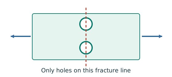
Prediction, then explanation. At fixed plate size, larger holes reduce the straight-path net area. A diagonal path needs its own stagger correction.
Subtract the hole widths crossed by the path, then multiply by thickness. Compare all plausible paths using the applicable course rule.
An is net area in mm²; b is plate width; d₀ is hole diameter; t is thickness, all in mm. n counts holes on this straight path.
Scope. This expression is for a straight cut. Effective area can require further shear-lag rules. Gross, net and effective areas must remain distinct.
Check and takeaway. Use the hole diameter, not the bolt diameter, when removing missing steel. The plate contains a hole, not solid steel around the bolt shank.
Apply the reasoning to this section’s data and conditions
Already factored?
Do not factor twice.
Mass or weight?
Convert only once.
Which support resists vertical force?
Which symbol only restrains lateral movement?
How many incoming beam reactions?
How many shear planes?
How many holes on this net section?
- Does the table row use flange thickness, web thickness, bolt diameter, or electrode class?
Are moments first-order or amplified?
Is the denominator elastic or plastic?
Is a missing restraint being disguised as a numerical assumption?
State it.