2022–2024 · Exam-focused route
2023 AQ1 — floor beams and fire protection
A complete 40-mark compulsory question.
The highest-value habit is tracing which beam receives each slab strip and reaction.
Marks are as printed in the paper; the working is a teaching guide, not an official marking scheme.
Read the load path before using a formula
Delay heat reaching the steel
Identify how the protection surrounds a steel section. Then explain its purpose in a fire.
Prediction, then explanation. An insulating layer can slow heating. It does not mean the steel remains at room temperature indefinitely.
Heat changes steel behaviour. Protection delays that change by restricting heat transfer. Show the steel and protection boundaries separately.
The labelled boundaries describe geometry. They do not specify a tested fire-resistance rating.
Scope. Required thickness depends on the system, member and required rating. Do not infer thickness or minutes from a schematic.
Check and takeaway. For a sketch answer, distinguish all three shapes and state that protection delays steel heating.
Find which plate buckles first
Before using plastic bending resistance, check whether the flange and web can sustain the required stress distribution.
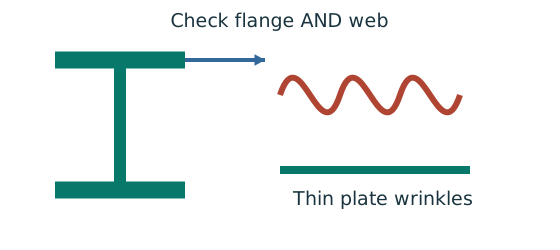
Prediction, then explanation. At fixed width, a thinner plate has a larger width-to-thickness ratio. Local buckling then becomes more restrictive.
Calculate the flange and web ratios separately. Compare each with the limits for its stress condition. The worse class governs.
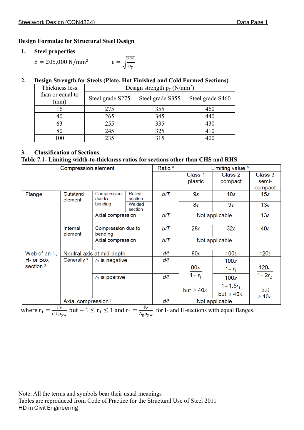
py is the design yield strength in N/mm². ε is a dimensionless scale used in the supplied classification limits.
Scope. Pure bending and uniform compression use different web limits. Class 2 allows plastic resistance but not the Class 1 rotation capability.
Check and takeaway. A Class 1 web and Class 2 flange give a Class 2 section. Do not average the class numbers.
A safe beam can still sag too far
Check whether the beam displacement exceeds the permitted service limit.
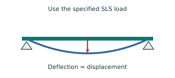
Prediction, then explanation. For the same UDL and stiffness, doubling span multiplies deflection by sixteen. Doubling I halves deflection.
Load bends each beam segment. The curvature accumulates along the span. Material stiffness E and geometric stiffness I resist that deformation.
Use w in N/mm, L in mm, E in N/mm² and I in mm⁴. The resulting midspan deflection is in mm.
Scope. The formula assumes a prismatic, simply supported, linear-elastic beam with full-span UDL. Use the stated service load and deflection limit.
Check and takeaway. A higher yield grade does not automatically increase E. Passing a strength check therefore does not prove acceptable deflection.
Apply the reasoning to this section’s data and conditions
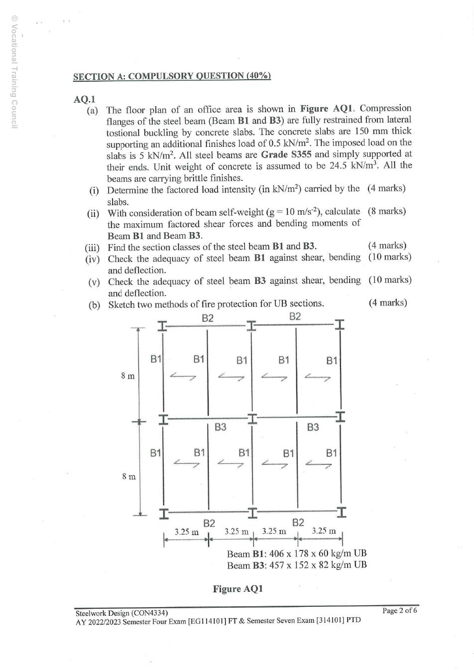
Given: 150 mm slab, concrete unit weight 24.5 kN/m³, finishes 0.5 kN/m², imposed load 5 kN/m²; S355 beams, simple end supports, full slab restraint to the compression flange and brittle finishes.
Find ULS actions, section classes, shear/bending resistance, imposed-load deflection, then sketch two fire-protection methods.
In the original plan, B1 spans 8 m.
Its tributary width is 3.25 m: half the adjacent strip on each side.
The central B3 span is 6.5 m, between the I-shaped column symbols.
At its midpoint, TWO B1 members meet from opposite sides, so add their two end reactions.
The slab load must not be applied to B3 a second time.
Physical interpretation and limits
Imagine the slab passing parcels to B1.
Each B1 passes half its parcels to each support.
The middle beam receives a parcel pile from each side.
Therefore, the piles add.
Its own weight is a separate load spread along its length.
Prerequisites: intensity × tributary width = line load; force × lever arm = moment.
Use kN and metres for statics.
Use N, mm and N/mm² for deflection and strength.
One kN/m equals one N/mm.
All intermediate values below are calculated without rounding until the displayed answer.
Collect the section data once
A table value has conditions
Find a design property without mixing a row, column or standard from a different case.
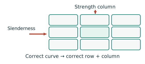
Prediction, then explanation. A different flange thickness can select a lower design strength even when the steel grade name remains unchanged.
Match the complete section designation. Read the relevant axis and unit. For strength tables, select material, thickness and curve before interpolating.
Given values come from the question. Lookup values come from a named table. Assumed values require an explicit condition.
Scope. A missing row or omitted restraint cannot be recovered from a schematic’s scale. Keep the result conditional when required data are absent.
Check and takeaway. Record the table, row, column and unit beside the substitution. That makes a later check possible.
Use the property for the physical question
A section table contains several numbers. Choose the property that matches the calculation and bending axis.
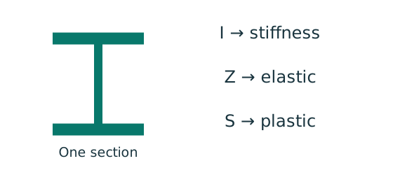
Prediction, then explanation. Moving equal area away from an axis increases I about that axis. It does not increase total area.
Each small area contributes its area multiplied by squared distance. Sum those contributions to obtain I.
I is second moment of area in mm⁴. y is distance from the chosen axis in mm. A is area in mm². r is radius of gyration in mm.
Scope. Z is elastic section modulus; S is plastic section modulus in this course. Neither is interchangeable with I.
Check and takeaway. A nominal section designation is a row identifier. Use the actual dimensions and units in that exact row.
Apply the reasoning to this section’s data and conditions
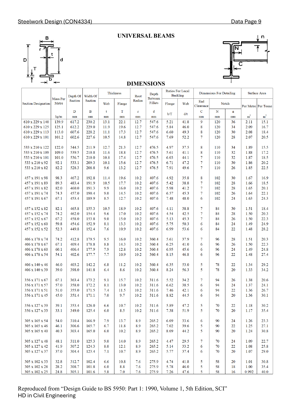
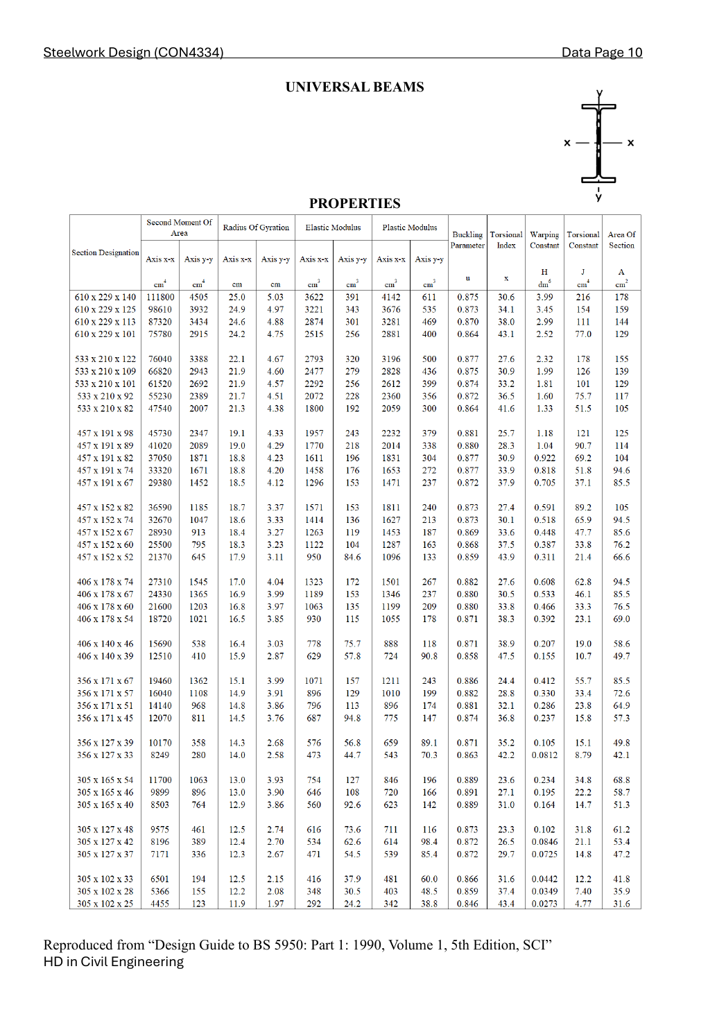
Look up the exact section designation, not the nearest depth.
The mass column gives 60.1 and 82.1 kg/m.
The rounded 60 and 82 in the names are labels.
The flange thickness selects the design-strength row.
E = 205,000 N/mm² is the course elastic modulus.
| Beam / section | Dimensions and ratios | Properties |
|---|---|---|
| B1 / 406 × 178 × 60 UB | ||
| B3 / 457 × 152 × 82 UB |
D is overall depth, t web thickness, T flange thickness, b flange outstand used by the table, d clear web depth, I second moment of area, Z elastic modulus and S plastic modulus.
The table gives centimetre-based I, Z and S; convert explicitly below.
AQ1(a)(i) — slab design intensity [4 marks]
Change the ruler, keep the quantity
A section table uses centimetres, but the strength calculation uses millimetres. The numbers must describe the same section.
Prediction, then explanation. Would every property increase by ten? No. The exponent determines how many factors of ten are needed.
First identify the physical quantity. Next convert each length factor. Keep force and length conversions separate when converting a moment.
Here n is the length exponent: 2 for area, 3 for section modulus and 4 for second moment of area.
Scope. Changing units changes neither the load nor the section. A conversion factor cannot repair a formula for the wrong physical quantity.
Check and takeaway. Illustration: . The fourth power belongs to the unit, not the number 2.
Use the same mechanism: A table value has conditions. A different flange thickness can select a lower design strength even when the steel grade name remains unchanged.
Ask two separate design questions
Decide whether the check concerns failure or unacceptable behaviour during use.
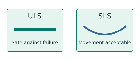
Prediction, then explanation. A larger section may improve both results, but a pass on one branch does not prove a pass on the other.
ULS addresses relevant strength and stability failure modes. SLS addresses specified service conditions such as deflection.
δ is the calculated displacement; δlimit is the permitted displacement. Both must use the same length unit.
Scope. Use each check’s own load combination and limit. A strength load factor does not change the physical stiffness.
Check and takeaway. Write separate conclusions for strength, stability and serviceability where requested. A single unexplained “safe” hides those distinctions.
Apply the reasoning to this section’s data and conditions
Convert slab thickness to metres before multiplying by concrete unit weight.
Apply the course gravity ULS factors once to characteristic permanent and imposed loads.
AQ1(a)(ii) — actions on both beams [8 marks]
Keep load categories separate
A floor carries permanent material and changing occupancy loads. Find the design load for the stated check.
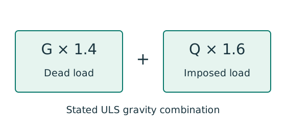
Prediction, then explanation. Increasing imposed load changes its own term. It does not change the dead-load factor or the steel stiffness.
First convert mass to weight where required. Next collect G and Q in compatible units. Apply the combination specified by the course problem.
G is characteristic dead load; Q is characteristic imposed load. Wu is the design load for this course gravity combination.
Scope. This combination is not universal. Use the specified service load for deflection and the stated factors for other standards or cases.
Check and takeaway. Illustration: G = 10 kN and Q = 5 kN give 22 kN. Factoring their sum by one guessed factor loses the distinction.
Balance the isolated beam
Find the two vertical reactions before calculating internal shear or moment.
Prediction, then explanation. Move the same load toward B. Reaction B increases because the load has a larger moment arm about A.
Take moments about A. Reaction A has zero lever arm there. Then use vertical force balance to find reaction A.
P, RA and RB are forces in kN. L is support spacing and a is load position, both in m.
Scope. These expressions describe one point load on a simply supported beam. Add other loads through equilibrium; keep their actual positions.
Check and takeaway. Illustration: P = 60 kN, L = 6 m and a = 2 m give RB = 20 kN and RA = 40 kN.
Use the same mechanism: Change the ruler, keep the quantity. Would every property increase by ten? No. The exponent determines how many factors of ten are needed.
Apply the reasoning to this section’s data and conditions
The mass-to-force conversion uses g = 10 m/s².
This is explicitly given in the 2023 paper.
The 2022 paper omits g.
Therefore, its numerical branch adopts the same course convention.
If a different g is supplied, replace only the self-weight terms.
For a simply supported beam with uniform load, equilibrium shares the total load equally.
The maximum sagging moment is at midspan.
B3 receives the two B1 reactions as ONE midspan point load.
Add its own factored self-weight as a UDL; superpose the two standard simple-beam solutions.
Check: the two reactions of the supporting beam equal its point load plus its total self-weight.
No extra slab UDL is added.
AQ1(a)(iii) — classification [4 marks]
Use the same mechanism: Find which plate buckles first. At fixed width, a thinner plate has a larger width-to-thickness ratio. Local buckling then becomes more restrictive.
Apply the reasoning to this section’s data and conditions
Use the material strength selected by flange thickness.
For a rolled I section in pure major-axis bending, Class 1 limits are 9ε for the compression-flange outstand and 80ε for the web.
Both must pass.
The web limit for uniform axial compression is different and must not be used here.
B1
B3
Both sections are Class 1.
Therefore, the low-shear bending check may use the plastic modulus, subject to the elastic-modulus cap.
AQ1(a)(iv) — B1 adequacy [10 marks]
Shear and bending share the web
Decide whether the unreduced bending resistance remains applicable at the section being checked.
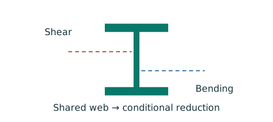
Prediction, then explanation. Raising shear beyond the specified threshold can reduce available bending resistance. A distant maximum shear is not the coexistent shear.
Find the moment-check position. Evaluate the shear there. Compare it with the low-shear threshold before selecting the resistance expression.
V is shear at the checked section; Vc is its shear resistance. Both use the same force unit.
Scope. Above the threshold, use the supplied reduction expression. The threshold itself is not a substitute resistance formula.
Check and takeaway. If the maximum shear anywhere is below the threshold, all sections satisfy that low-shear condition. Otherwise check the actual positions.
Use the same mechanism: A safe beam can still sag too far. For the same UDL and stiffness, doubling span multiplies deflection by sixteen. Doubling I halves deflection.
Vertical bending can trigger sideways motion
A beam has enough local bending resistance. Check whether its compression flange can move sideways and twist.
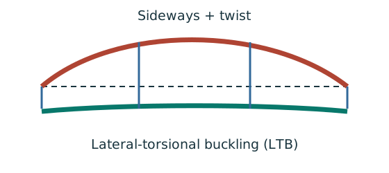
Prediction, then explanation. Adding a valid lateral restraint shortens a stability segment. It need not change the beam’s vertical reaction or moment diagram.
Identify the compressed flange and effective restraints. Calculate the specified slenderness, read buckling strength and compare resistance with the segment demand.
LE and ry use the same length unit. pb uses N/mm²; Sx uses mm³; Mb uses N·mm. mLT is dimensionless.
Scope. Use the specified section class, effective-length branch and loading condition. Load height alone does not prove a destabilizing case.
Check and takeaway. Removing a lateral restraint requires a new segment stability check. The old shorter-segment result cannot establish the longer segment’s adequacy.
Apply the reasoning to this section’s data and conditions
Shear is carried mainly by the web.
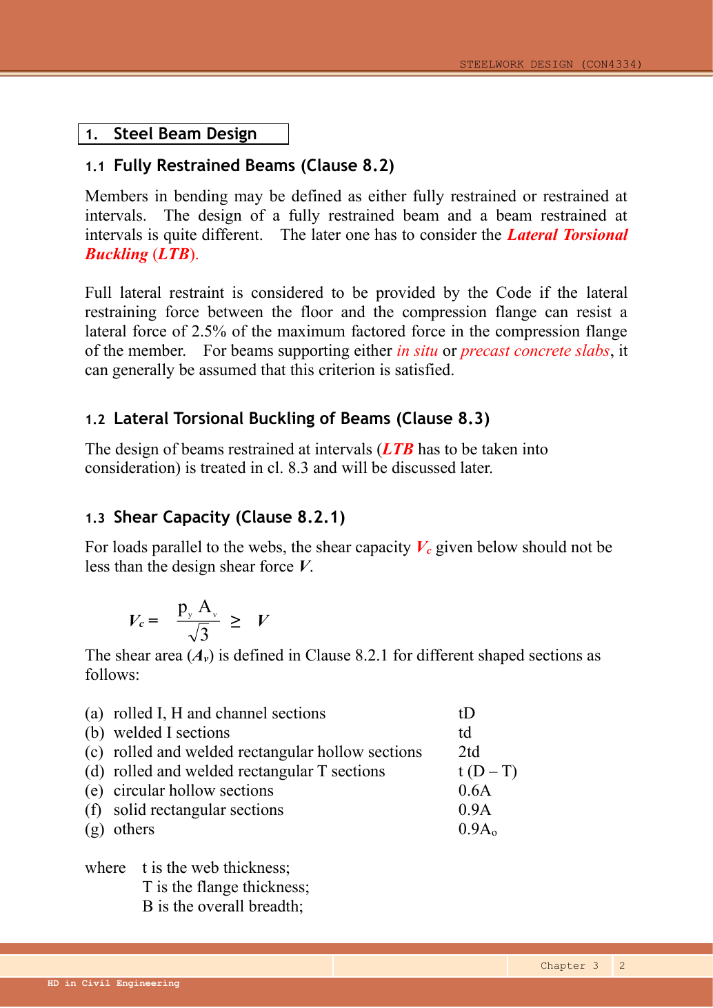
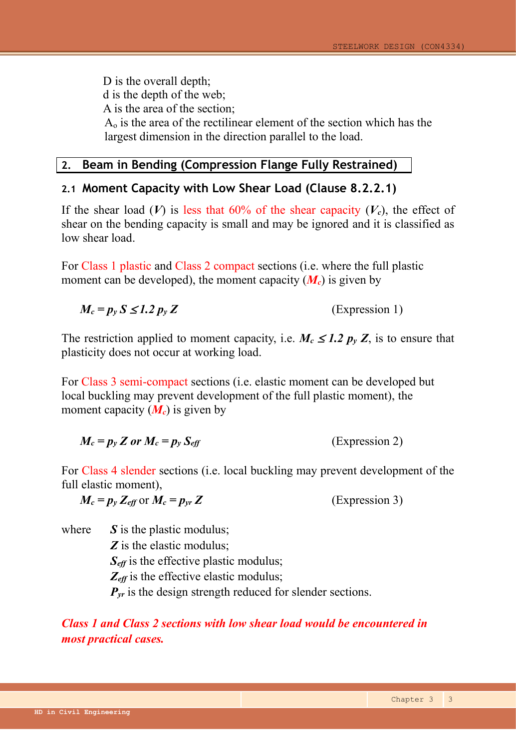
The course rolled-I shear area is overall depth times web thickness.
Multiply area by shear strength, then divide by 1,000 to obtain kN.
Shear passes and lies in the low-shear range, so no high-shear reduction is needed.
Full slab restraint is given.
This question needs section bending resistance, not an unrestrained-beam LTB calculation.
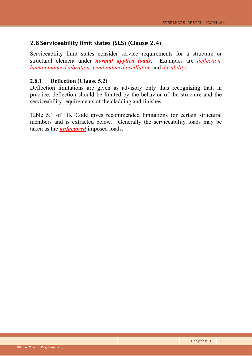
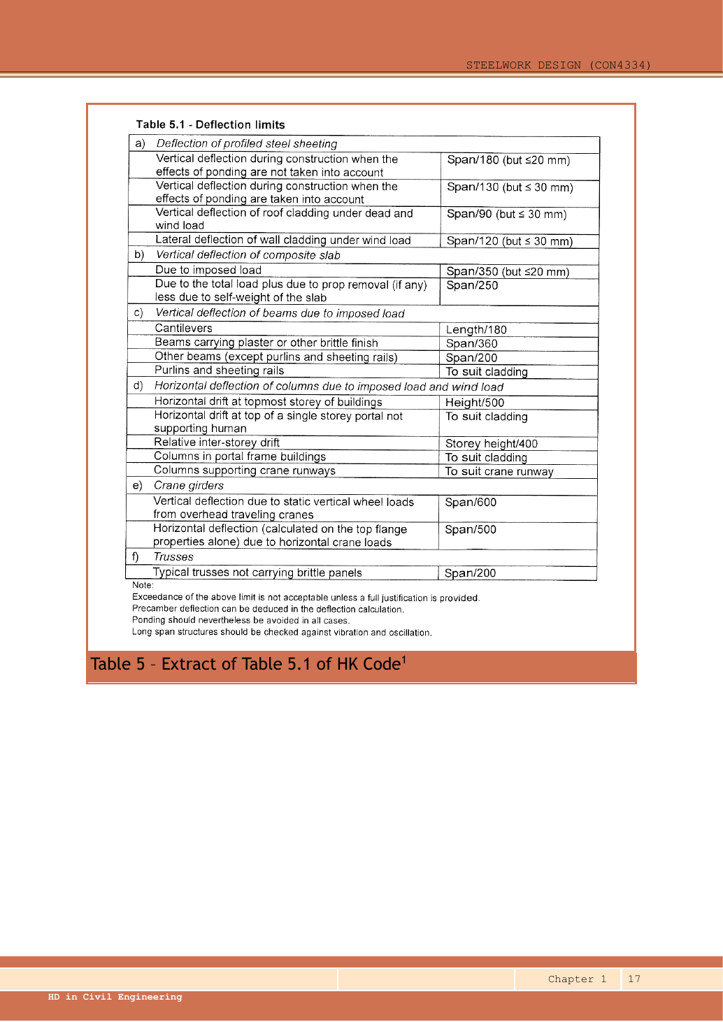
For the course brittle-finish deflection check, use unfactored imposed loading and the span/360 limit.
ULS load factors and permanent-load self-weight do not enter this particular incremental-deflection calculation.
This does not certify a separately specified total-deflection limit.
All three requested checks pass under the stated load model.
AQ1(a)(v) — B3 adequacy [10 marks]
Use the same mechanism: Shear and bending share the web. Raising shear beyond the specified threshold can reduce available bending resistance. A distant maximum shear is not the coexistent shear.
Use the same mechanism: A safe beam can still sag too far. For the same UDL and stiffness, doubling span multiplies deflection by sixteen. Doubling I halves deflection.
Use the same mechanism: Vertical bending can trigger sideways motion. Adding a valid lateral restraint shortens a stability segment. It need not change the beam’s vertical reaction or moment diagram.
Apply the reasoning to this section’s data and conditions
Shear is carried mainly by the web.
The course rolled-I shear area is overall depth times web thickness.
Multiply area by shear strength, then divide by 1,000 to obtain kN.
Shear passes and lies in the low-shear range, so no high-shear reduction is needed.
Full slab restraint is given.
This question needs section bending resistance, not an unrestrained-beam LTB calculation.
For the course brittle-finish deflection check, use unfactored imposed loading and the span/360 limit.
ULS load factors and permanent-load self-weight do not enter this particular incremental-deflection calculation.
This does not certify a separately specified total-deflection limit.
All three requested checks pass under the stated load model.
AQ1(b) — two fire-protection methods [4 marks]
Use the same mechanism: Delay heat reaching the steel. An insulating layer can slow heating. It does not mean the steel remains at room temperature indefinitely.
Apply the reasoning to this section’s data and conditions
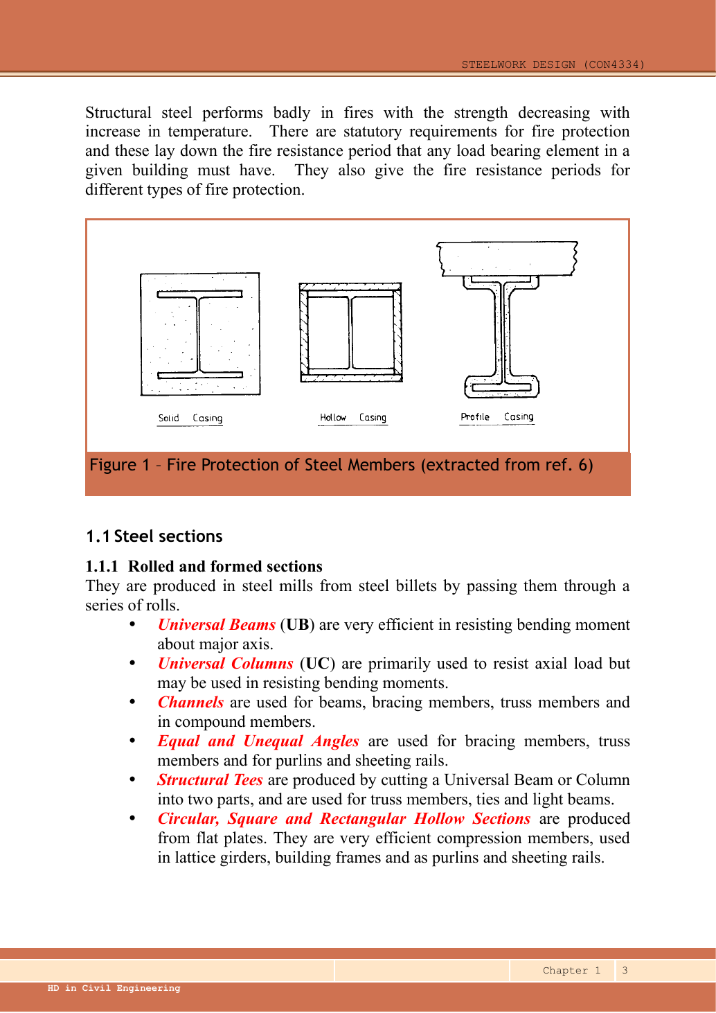
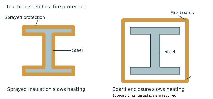
Teaching sketches: an insulating coating follows the steel profile; protective boards enclose the steel with supported joints.
Sprayed fire-resisting material: draw the I section with a continuous external insulation layer.
Label steel, sprayed protection and exposure to fire.
The layer slows heat transfer to steel so it retains useful strength for longer.
Board encasement: draw a box around the I section, identify fire-resisting boards and their supports/joints.
The enclosure delays heating.
Do not claim a specific fire-resistance duration without a specified tested system.
These are model explanations for the printed four-mark task.
The paper supplies no official subdivision of marks.
Result and concise exam wording
Follow one strip of floor
An area load must become a beam load before beam reactions can be calculated.
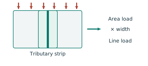
Prediction, then explanation. At fixed area load, twice the tributary width gives twice the line load. An end reaction remains a concentrated force.
Consider one metre along the beam. The associated floor area is b square metres. Multiply area load by that width.
q is area load in kN/m²; b is tributary width in m; w is line load in kN/m.
Scope. Determine b from slab spanning and supports. Add beam self-weight separately. A secondary-beam reaction is not automatically a UDL.
Check and takeaway. Illustration: . The width cancels one length unit.
Use the same mechanism: Keep load categories separate. Increasing imposed load changes its own term. It does not change the dead-load factor or the steel stiffness.
Apply the reasoning to this section’s data and conditions
Concise exam wording
Actions above are in kN and kN·m respectively.
Both sections Class 1.
B1: Pv 658.034 kN, Mc 425.645 kN·m, δ 19.572 mm < 22.222 mm.
B3: Pv 974.198 kN, Mc 624.795 kN·m, δ 9.916 mm < 18.056 mm.
Both pass.
State g=10 and the two-reaction load path.
For (b), give the two labelled sketches and explain delayed heating.
Misconceptions and checks
Use the same mechanism: A safe beam can still sag too far. For the same UDL and stiffness, doubling span multiplies deflection by sixteen. Doubling I halves deflection.
Use the same mechanism: Keep load categories separate. Increasing imposed load changes its own term. It does not change the dead-load factor or the steel stiffness.
Use the same mechanism: Change the ruler, keep the quantity. Would every property increase by ten? No. The exponent determines how many factors of ten are needed.
Apply the reasoning to this section’s data and conditions
- Do not use just one B1 reaction at the middle beam.
- Do not use ultimate loads in the imposed-load deflection check.
- Do not confuse cm⁴ with mm⁴: the conversion factor is 10,000.
Procedure for a new variant
Use the same mechanism: Find which plate buckles first. At fixed width, a thinner plate has a larger width-to-thickness ratio. Local buckling then becomes more restrictive.
Use the same mechanism: A safe beam can still sag too far. For the same UDL and stiffness, doubling span multiplies deflection by sixteen. Doubling I halves deflection.
Use the same mechanism: Keep load categories separate. Increasing imposed load changes its own term. It does not change the dead-load factor or the steel stiffness.
Apply the reasoning to this section’s data and conditions
- Trace slab → B1 → supporting beam → columns.
- Factor gravity loads, include each beam self-weight once, then solve statics.
- Classify, check shear range, bending and unfactored deflection.
Prediction with explained answer — invented variant
Use the same mechanism: A safe beam can still sag too far. For the same UDL and stiffness, doubling span multiplies deflection by sixteen. Doubling I halves deflection.
A force couple carries moment
Separate the force couple used to carry moment from the force used to carry web shear.
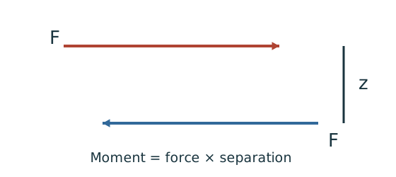
Prediction, then explanation. For the same moment, a larger lever arm requires a smaller couple force. It does not remove the web shear.
Moment is force multiplied by perpendicular separation. Divide the required moment by the specified separation to obtain each couple force.
M is moment in kN·mm; z is the specified force-line separation in mm; F is force in kN.
Scope. Use the lever arm defined by the source model. Do not silently replace it with overall section depth or another geometric distance.
Check and takeaway. Check flange welds for the couple forces and web welds for the stated shear model. Both force paths need a satisfactory detail.
Use the same mechanism: Balance the isolated beam. Move the same load toward B. Reaction B increases because the load has a larger moment arm about A.
Apply the reasoning to this section’s data and conditions
Invented change: the middle beam receives only one B1 end reaction, with every other input unchanged.
Which terms halve?
Hint
Separate the point-load solution from the self-weight UDL solution.
Answer and reasoning
Its B1 point-load contribution to shear, moment and live-load deflection halves.
Its own-weight UDL contribution does not halve.
B1 actions do not change.
Recalculate by replacing the two-reaction point load with one reaction.