2022–2024 · Exam-focused route
2022 BQ1(a) — double-cover bolted splice
Check the four requested strength modes for the given 960 kN splice.
Marks are as printed in the paper; the working is a teaching guide, not an official marking scheme.
Read the splice and choose one complete load path
Count cuts through each loaded bolt
Find how many shear planes transfer the force through one side of the connection.
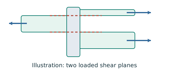
Prediction, then explanation. For equal sharing and unchanged bolt area, two active planes provide twice one plane’s shear resistance.
Select the area at the actual shear plane. Multiply by bolt shear strength. Count only the bolts and planes in the same transfer stage.
ps is bolt shear strength in N/mm²; As is the appropriate area in mm². nb counts bolts; ns counts equally loaded shear planes.
Scope. Use the thread area when threads cross the plane as required. Check bearing, plate failure and detailing separately.
Check and takeaway. Both halves of a butt splice carry the full transmitted force in sequence. Counting both halves together would double the apparent resistance.
Follow contact pressure into the plate
The bolt may survive shear while the connected plate deforms or tears near the hole.
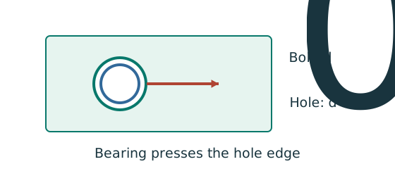
Prediction, then explanation. At fixed geometry and strength, a thicker plate raises plate resistance. Moving a hole too near the end can still govern.
Calculate every bound required by the supplied rule. The smallest applicable bound limits the connection at that layer.
pbs is the applicable bearing strength in N/mm²; d is nominal bolt diameter in mm; t is plate thickness in mm.
Scope. This diameter term alone is not the complete check. End-distance and clear-ligament limits, bolt bearing and each connected layer also matter.
Check and takeaway. Two covers and one main plate do not necessarily have the same thickness or strength. Compare the actual force share in each layer.
Test every possible fracture cut
Find the remaining steel area across a candidate tension-failure path.
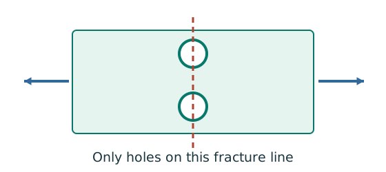
Prediction, then explanation. At fixed plate size, larger holes reduce the straight-path net area. A diagonal path needs its own stagger correction.
Subtract the hole widths crossed by the path, then multiply by thickness. Compare all plausible paths using the applicable course rule.
An is net area in mm²; b is plate width; d₀ is hole diameter; t is thickness, all in mm. n counts holes on this straight path.
Scope. This expression is for a straight cut. Effective area can require further shear-lag rules. Gross, net and effective areas must remain distinct.
Check and takeaway. Use the hole diameter, not the bolt diameter, when removing missing steel. The plate contains a hole, not solid steel around the bolt shank.
Apply the reasoning to this section’s data and conditions
Given ultimate tension 960 kN: do not factor it again.
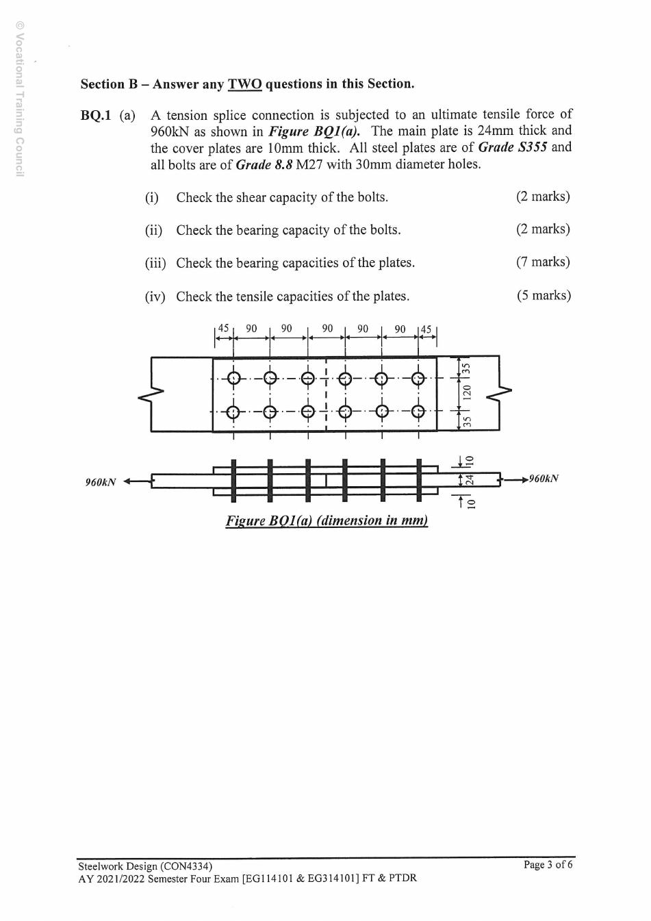
The side elevation shows a 24 mm main plate between two 10 mm covers.
The plan has two bolt rows, gauge 120 mm and side edges 35 mm each.
Therefore, the width is 190 mm.
Three bolt columns lie on each side of the butt joint: six bolts per half, twelve physically.
Each half transfers the full force.
Each cover carries 480 kN.
Physical interpretation and limits
Two groups in series act like two links in a chain: the same force passes through each.
The two identical covers act in parallel and share the force.
These are different reasons for a factor of two.
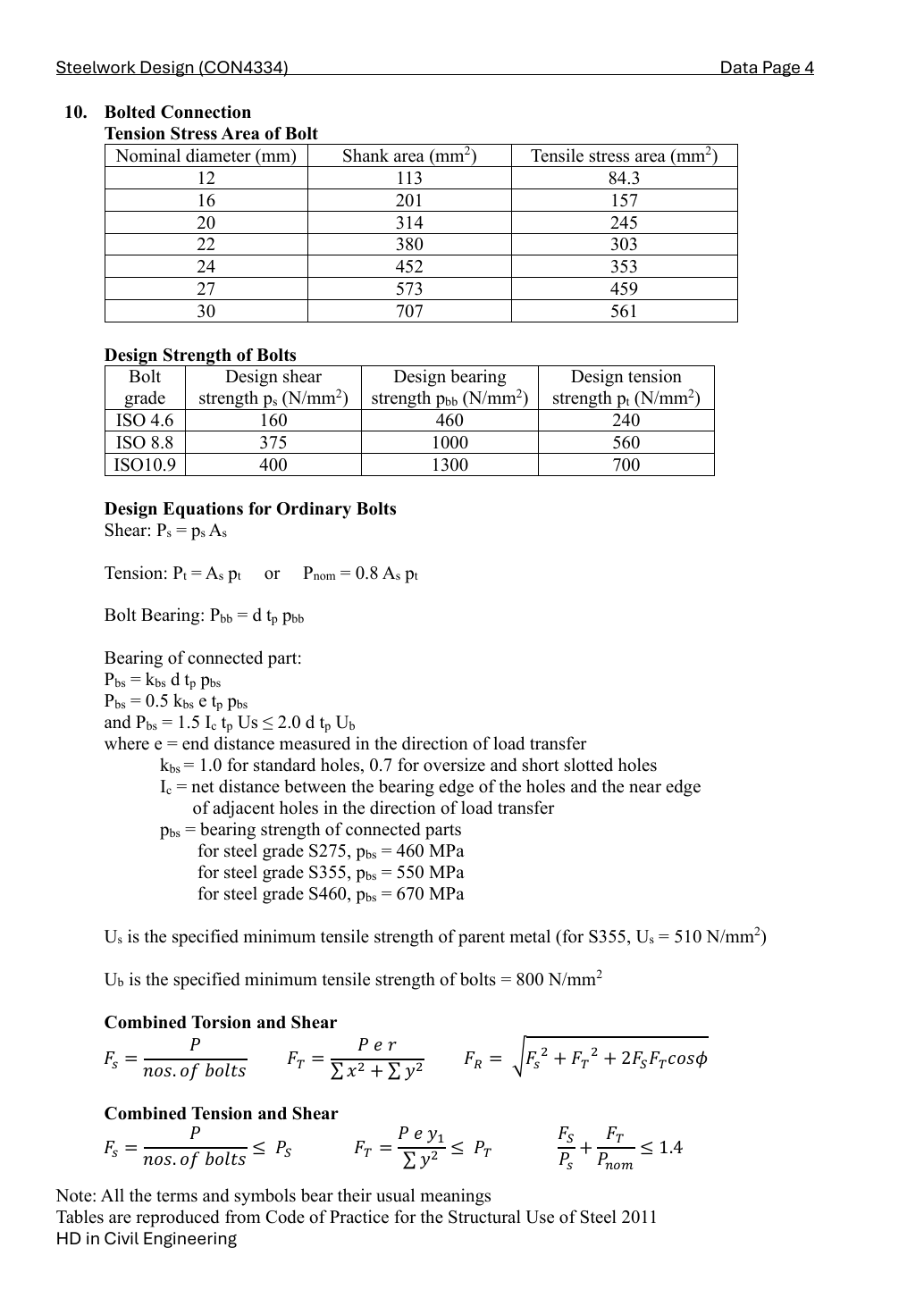
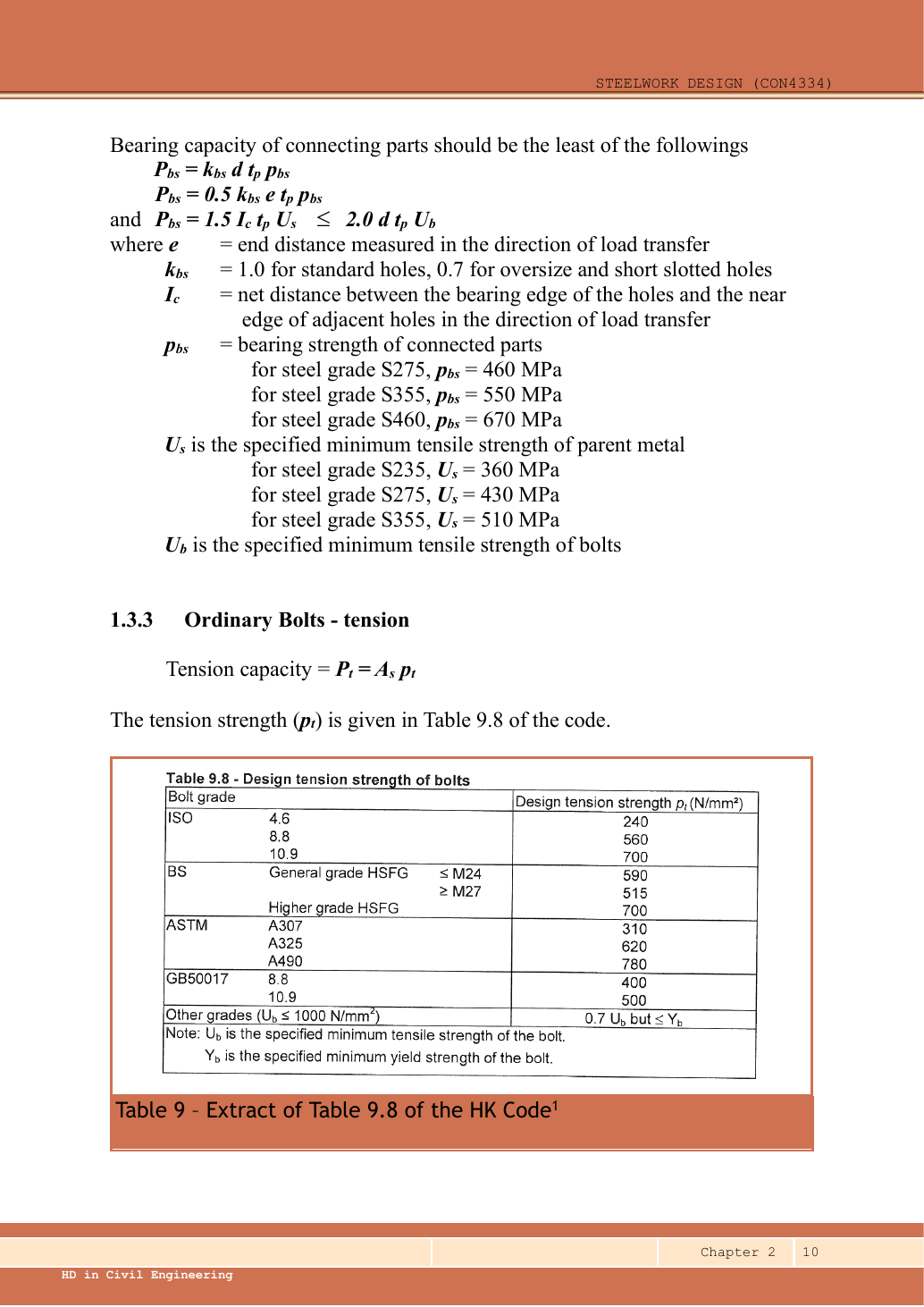
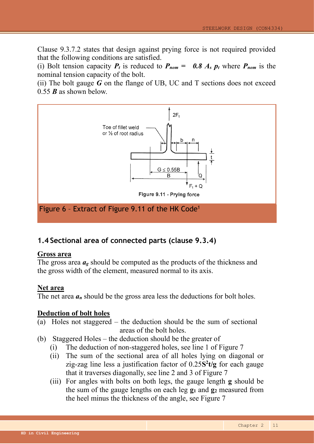
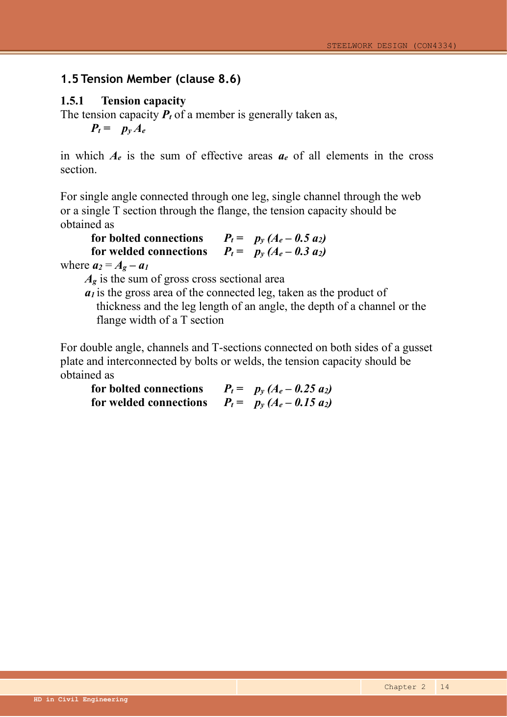
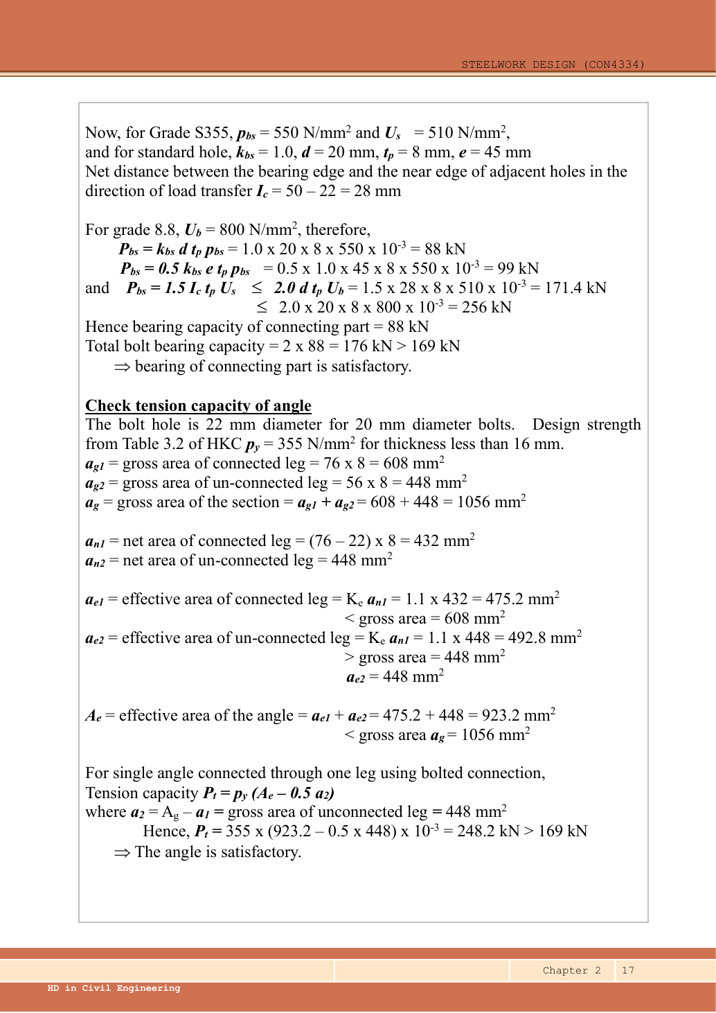
Lookups: Data File p.4, M27 tensile-stress-area row and ISO 8.8 strength row.
Use thread area conservatively because a thread-free shear plane is not specified.
For S355 plate bearing use 550 N/mm² and ultimate parent-metal strength 510 N/mm²; bolt ultimate strength is 800 N/mm².
Ordinary 30 mm holes for M27 give the standard-hole factor one.
Symbols: d is bolt diameter; d₀ hole diameter; Aₛ bolt stress area; pₛ shear strength; pbb bolt bearing strength; pbs connected-part bearing strength; Ke net-area coefficient.
Subtract d₀ from metal width, but use d in bearing resistance.
Stress × mm² gives N; divide by 1,000 for kN.
BQ1(a)(i) — bolt shear [2 marks]
Use the same mechanism: Count cuts through each loaded bolt. For equal sharing and unchanged bolt area, two active planes provide twice one plane’s shear resistance.
Apply the reasoning to this section’s data and conditions
The main-to-cover interfaces create two shear planes per bolt.
Count six bolts on one half-splice.
BQ1(a)(ii) — bolt bearing [2 marks]
Use the same mechanism: Follow contact pressure into the plate. At fixed geometry and strength, a thicker plate raises plate resistance. Moving a hole too near the end can still govern.
Apply the reasoning to this section’s data and conditions
Compare the middle-ply bearing thickness with the sum of the two symmetric outer plies.
This is not an extra shear-plane multiplier.
BQ1(a)(iii) — plate bearing [7 marks]
Use the same mechanism: Follow contact pressure into the plate. At fixed geometry and strength, a thicker plate raises plate resistance. Moving a hole too near the end can still govern.
Apply the reasoning to this section’s data and conditions
The dimension chain gives pitch 90 mm and COVER end distance 45 mm.
The main-plate butt line is drawn between the central bolt columns.
However, its offset is not separately dimensioned.
For a centred-butt teaching branch, explicitly assume its two offsets are 45 mm.
Do not infer this equality from drawing scale.
Check the 24 mm main plate and each 10 mm cover separately.
The end distance is measured parallel to the force, from the free end to the nearest bolt centre.
The clear inter-hole ligament is pitch minus one hole diameter.
Use the smallest applicable bound; using the end-bolt bound for every bolt is conservative for the interior bolts.
Without the centred-butt assumption, keep the nearer main-plate end distance e as an unknown.
The demanded resistance per bolt is 160 kN; all other bounds exceed this.
The strength-only condition below is necessary for this conservative equal-load model.
The end distance is measured parallel to the force, from the free end to the nearest bolt centre.
The clear inter-hole ligament is pitch minus one hole diameter.
Use the smallest applicable bound; using the end-bolt bound for every bolt is conservative for the interior bolts.
BQ1(a)(iv) — plate tension [5 marks]
Use the same mechanism: Test every possible fracture cut. At fixed plate size, larger holes reduce the straight-path net area. A diagonal path needs its own stagger correction.
Apply the reasoning to this section’s data and conditions
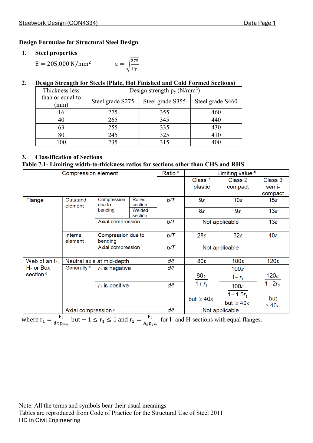
A transverse fracture line crosses TWO holes, one in each row.
It does not cross all six holes on a half-splice.
Effective area is the smaller of Ke times net area and gross area.
The 24 mm main plate uses design strength 345 N/mm².
Each 10 mm cover uses 355 N/mm².
Under the stated centred-butt branch, the requested strength checks pass; cover tension governs.
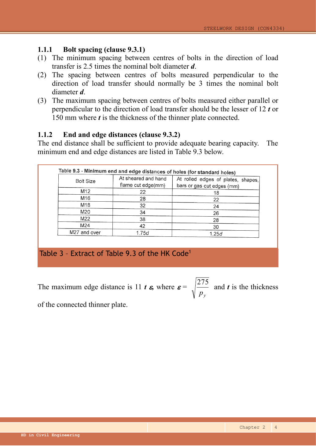
This is not a blanket detailing approval: the 35 mm side edge and 45 mm end pass the rolled/gas-cut M27 minimum 33.75 mm.
However, not the sheared/hand-flame-cut minimum 47.25 mm.
The cutting method is absent.
Result and concise exam wording
Use the same mechanism: Test every possible fracture cut. At fixed plate size, larger holes reduce the straight-path net area. A diagonal path needs its own stagger correction.
Apply the reasoning to this section’s data and conditions
Concise exam wording
In the centred-butt branch all exceed 960 kN.
Cover tension governs; state the assumed main-plate end distance and unspecified edge preparation.
Misconceptions and checks
Use the same mechanism: Count cuts through each loaded bolt. For equal sharing and unchanged bolt area, two active planes provide twice one plane’s shear resistance.
Use the same mechanism: Follow contact pressure into the plate. At fixed geometry and strength, a thicker plate raises plate resistance. Moving a hole too near the end can still govern.
Apply the reasoning to this section’s data and conditions
- Do not sum both half-splice groups as parallel resistance.
- Do not use the hole diameter in bearing formulas.
Procedure for a new variant
Use the same mechanism: Test every possible fracture cut. At fixed plate size, larger holes reduce the straight-path net area. A diagonal path needs its own stagger correction.
Apply the reasoning to this section’s data and conditions
- Identify interfaces and load sharing.
- Check bolts and each plate path, then the transverse net section.
- Compare the minimum with demand and state detailing limits.
Prediction with explained answer — invented variant
Use the same mechanism: Follow contact pressure into the plate. At fixed geometry and strength, a thicker plate raises plate resistance. Moving a hole too near the end can still govern.
Use the same mechanism: Test every possible fracture cut. At fixed plate size, larger holes reduce the straight-path net area. A diagonal path needs its own stagger correction.
Apply the reasoning to this section’s data and conditions
Invented variant: demand rises to 1,050 kN without changing the joint.
What fails first?
Hint
Find the smallest complete-path resistance.
Answer and reasoning
The two covers fail the tension check.
The main plate and the calculated bolt/bearing checks still pass.