2014–2019 · Reference answers
2017-05-19 — connection answers
All connection subparts from this paper, including the specified checks and source qualifications.
Independent teaching answer, not an official solution or marking scheme.
Printed marks are retained.
Read the source conditions beside each result.
Recognise the connection model
Add force components at each bolt
An in-plane load acts away from the bolt-group centre. Find the largest resultant bolt force.
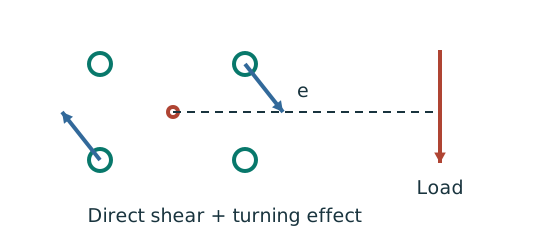
Prediction, then explanation. At fixed force, increasing eccentricity increases the moment component. Its direction differs between bolts.
Locate the bolt-group centre and coordinates. Add horizontal components together and vertical components together before finding each resultant.
e, xi and yi use mm; J uses mm². With M in kN·mm, each moment-force component is in kN.
Scope. These expressions use the stated elastic, equal-bolt in-plane model. Out-of-plane tension and prying require another model.
Check and takeaway. Do not add force magnitudes before resolving directions. Two perpendicular forces of 3 and 4 kN give 5 kN, not 7 kN.
An eccentric bracket pulls bolts differently
An out-of-plane moment rotates the bracket about the stated pivot. Determine the bolt tension pattern.
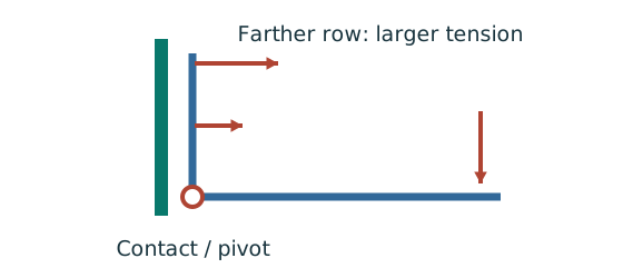
Prediction, then explanation. For unchanged geometry, doubling the applied moment doubles the modelled bolt tensions. Changing the pivot changes the distribution.
Use compatibility to relate tension to distance. Moment equilibrium then determines the proportionality factor.
M is moment in kN·mm. yi is distance from the stated pivot in mm. Ft,i is tension in kN.
Scope. Apply only to the stated active bolt set and pivot model. Flexible plates can create prying; use the supplied assumptions and resistance definitions.
Check and takeaway. A bolt’s lever arm is measured from the pivot used in the equation. It is not automatically its distance from the group centroid.
Test every possible fracture cut
Find the remaining steel area across a candidate tension-failure path.
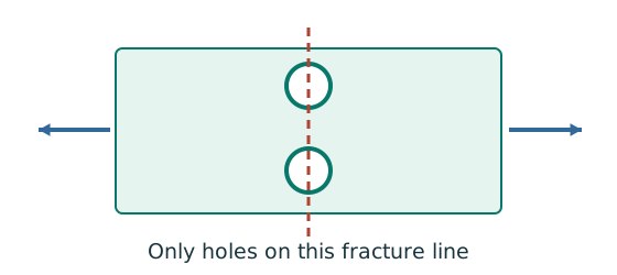
Prediction, then explanation. At fixed plate size, larger holes reduce the straight-path net area. A diagonal path needs its own stagger correction.
Subtract the hole widths crossed by the path, then multiply by thickness. Compare all plausible paths using the applicable course rule.
An is net area in mm²; b is plate width; d₀ is hole diameter; t is thickness, all in mm. n counts holes on this straight path.
Scope. This expression is for a straight cut. Effective area can require further shear-lag rules. Gross, net and effective areas must remain distinct.
Check and takeaway. Use the hole diameter, not the bolt diameter, when removing missing steel. The plate contains a hole, not solid steel around the bolt shank.
Apply the reasoning to this section’s data and conditions
Units: 1 kN = 1,000 N; 1 m = 1,000 mm; 1 cm³ = 1,000 mm³; 1 cm⁴ = 10,000 mm⁴.
Demand is the load effect.
Resistance is the permitted capacity for the selected failure mode.
Compare matching units.
A splice transfers axial force through stages.
A side-plate bracket creates in-plane torsion.
An end-plate bracket creates bolt tension.
Identify which picture applies before selecting a formula.
Plate tension [5 marks]
Use the same mechanism: Test every possible fracture cut. At fixed plate size, larger holes reduce the straight-path net area. A diagonal path needs its own stagger correction.
Apply the reasoning to this section’s data and conditions
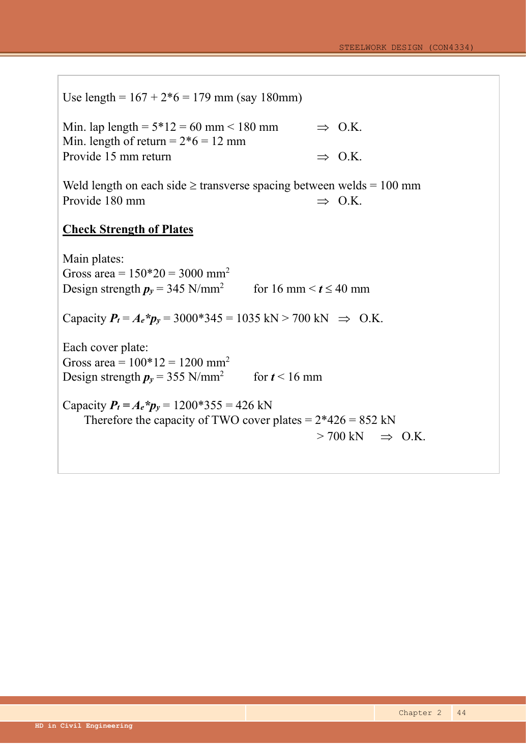
The main plate width is 170 mm.
Each cover is 120 mm wide, with thicknesses 18 mm and 10 mm respectively.
These come from the original width and side-view dimension chains.
There are no bolt holes.
The two covers act in parallel and each carries half the design tension.
Main: PASS; covers: PASS
Result and concise exam wording — key result lines
Main: PASS; covers: PASS
Weld design [4 marks]
The weld resists through its throat
Convert a visible fillet leg into resistance per effective length.
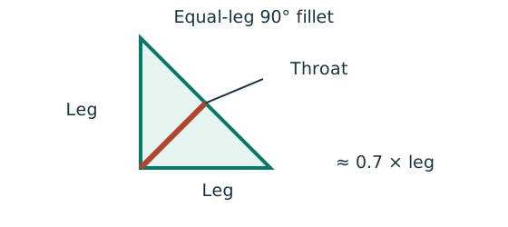
Prediction, then explanation. At fixed weld strength, doubling the leg doubles throat and line resistance in this model. Detailing limits can prevent that choice.
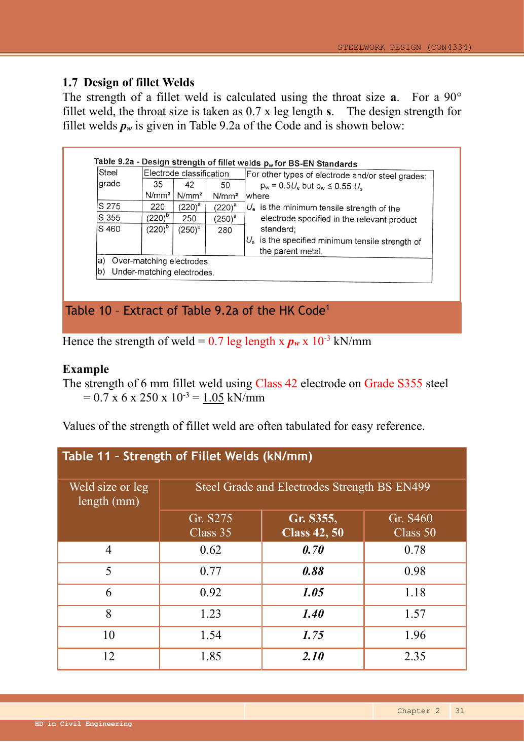
For the course right-angle equal-leg fillet, take throat as 0.7 times leg. Multiply throat area per unit length by weld strength.
s and a are leg and throat in mm. pw is weld strength in N/mm². qcap is resistance in kN/mm.
Scope. Use effective length, the correct steel/electrode strength and permitted leg limits. Full-penetration butt welds use a different model.
Check and takeaway. Illustration: a 6 mm leg at 250 N/mm² gives .
Apply the reasoning to this section’s data and conditions
Use longitudinal welds along both edges of each cover on each side of the butt.
Four parallel runs transfer the full force on one half.
The other half transfers the same force at the next stage of the path.
Count four runs in one transfer stage.
Adding both sequential stages would count the same transferred force twice.
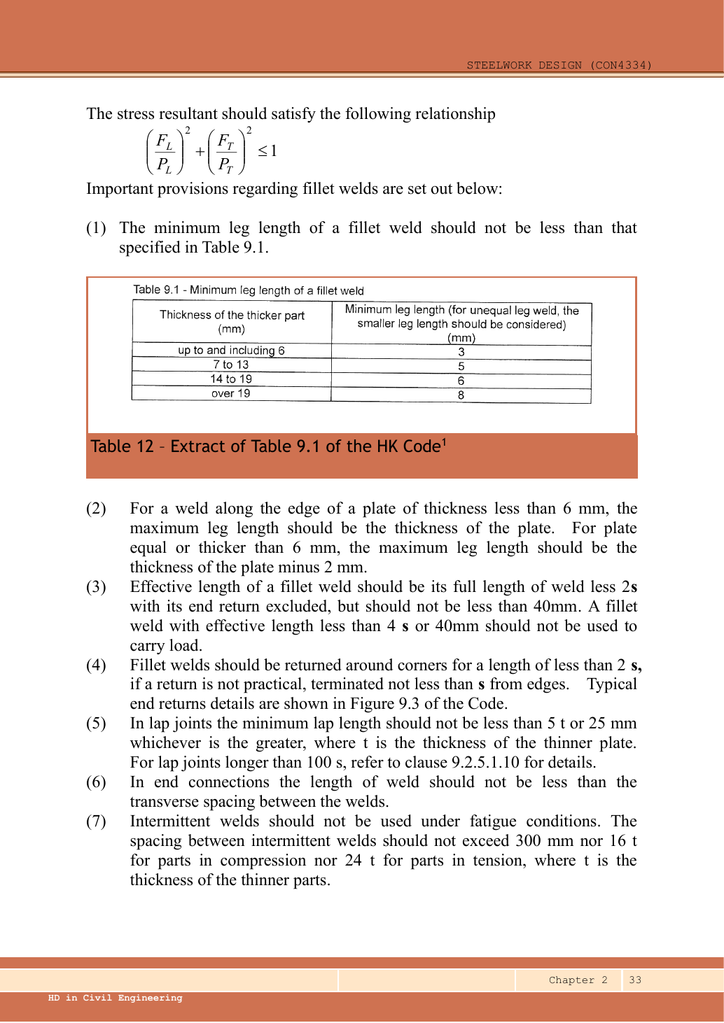
Provide enough effective length for force, minimum effective length and transverse weld spacing.
Add 2s to each run and round UP to 5 mm.
This is a designed arrangement, not an unstated original length.
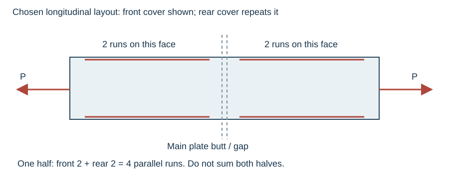
Teaching sketch: four longitudinal runs per half, two on each cover.
L is each physical run.
The butt gap is excluded.
Result and concise exam wording — key result lines
Provide enough effective length for force, minimum effective length and transverse weld spacing.
Add 2s to each run and round UP to 5 mm.
This is a designed arrangement, not an unstated original length.
Welding arrangement [4 marks]
Use the same mechanism: The weld resists through its throat. At fixed weld strength, doubling the leg doubles throat and line resistance in this model. Detailing limits can prevent that choice.
Apply the reasoning to this section’s data and conditions
Teaching sketch: four longitudinal runs per half, two on each cover.
L is each physical run.
The butt gap is excluded.
Repeat the two longitudinal runs on the hidden cover.
Size the lap for each side separately.
Do not run a counted load-carrying length across the unsupported butt gap.
Result and concise exam wording — key result lines
Repeat the two longitudinal runs on the hidden cover.
Size the lap for each side separately.
Do not run a counted load-carrying length across the unsupported butt gap.
One-plate actions [2 marks]
Use the same mechanism: Add force components at each bolt. At fixed force, increasing eccentricity increases the moment component. Its direction differs between bolts.
Count cuts through each loaded bolt
Find how many shear planes transfer the force through one side of the connection.
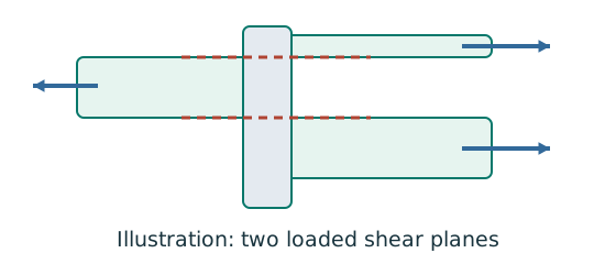
Prediction, then explanation. For equal sharing and unchanged bolt area, two active planes provide twice one plane’s shear resistance.
Select the area at the actual shear plane. Multiply by bolt shear strength. Count only the bolts and planes in the same transfer stage.
ps is bolt shear strength in N/mm²; As is the appropriate area in mm². nb counts bolts; ns counts equally loaded shear planes.
Scope. Use the thread area when threads cross the plane as required. Check bearing, plate failure and detailing separately.
Check and takeaway. Both halves of a butt splice carry the full transmitted force in sequence. Counting both halves together would double the apparent resistance.
Follow contact pressure into the plate
The bolt may survive shear while the connected plate deforms or tears near the hole.
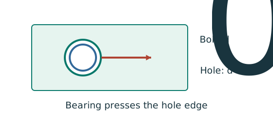
Prediction, then explanation. At fixed geometry and strength, a thicker plate raises plate resistance. Moving a hole too near the end can still govern.
Calculate every bound required by the supplied rule. The smallest applicable bound limits the connection at that layer.
pbs is the applicable bearing strength in N/mm²; d is nominal bolt diameter in mm; t is plate thickness in mm.
Scope. This diameter term alone is not the complete check. End-distance and clear-ligament limits, bolt bearing and each connected layer also matter.
Check and takeaway. Two covers and one main plate do not necessarily have the same thickness or strength. Compare the actual force share in each layer.
Apply the reasoning to this section’s data and conditions
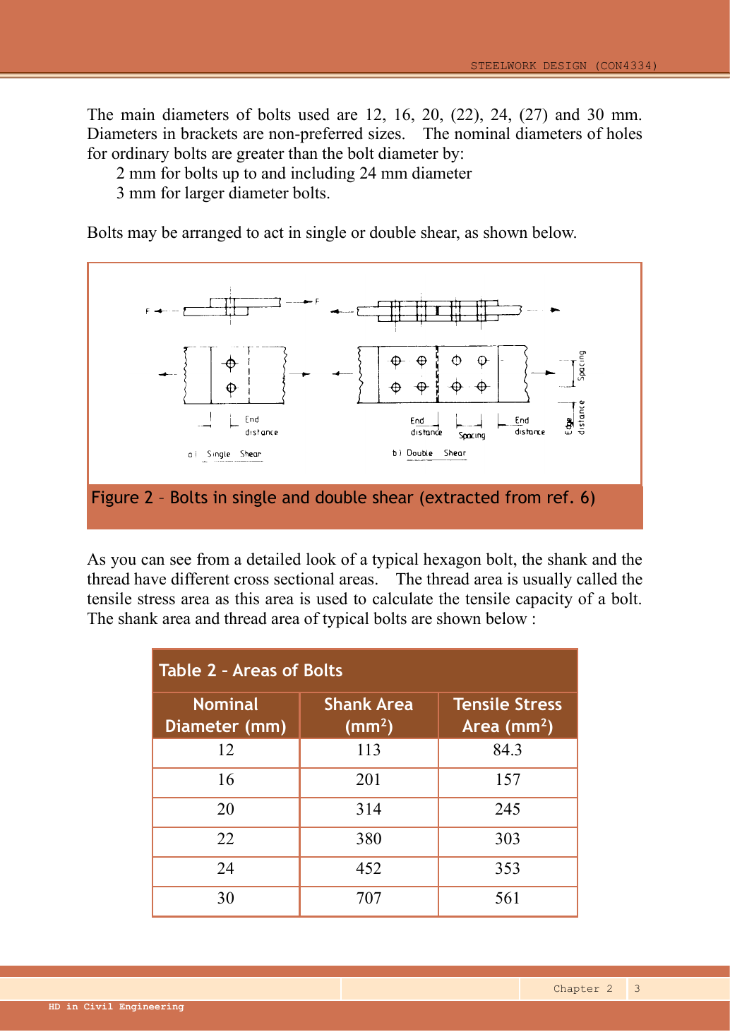
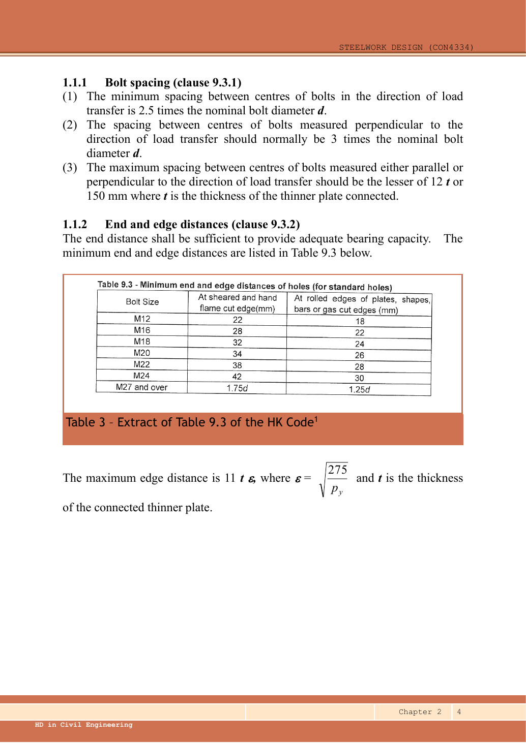
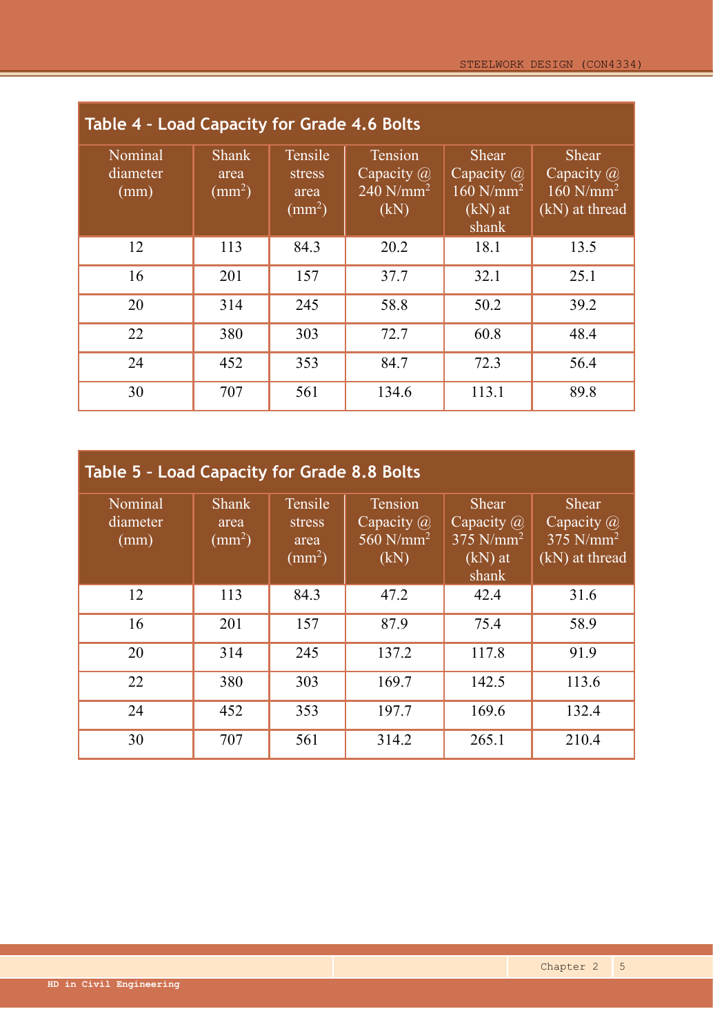
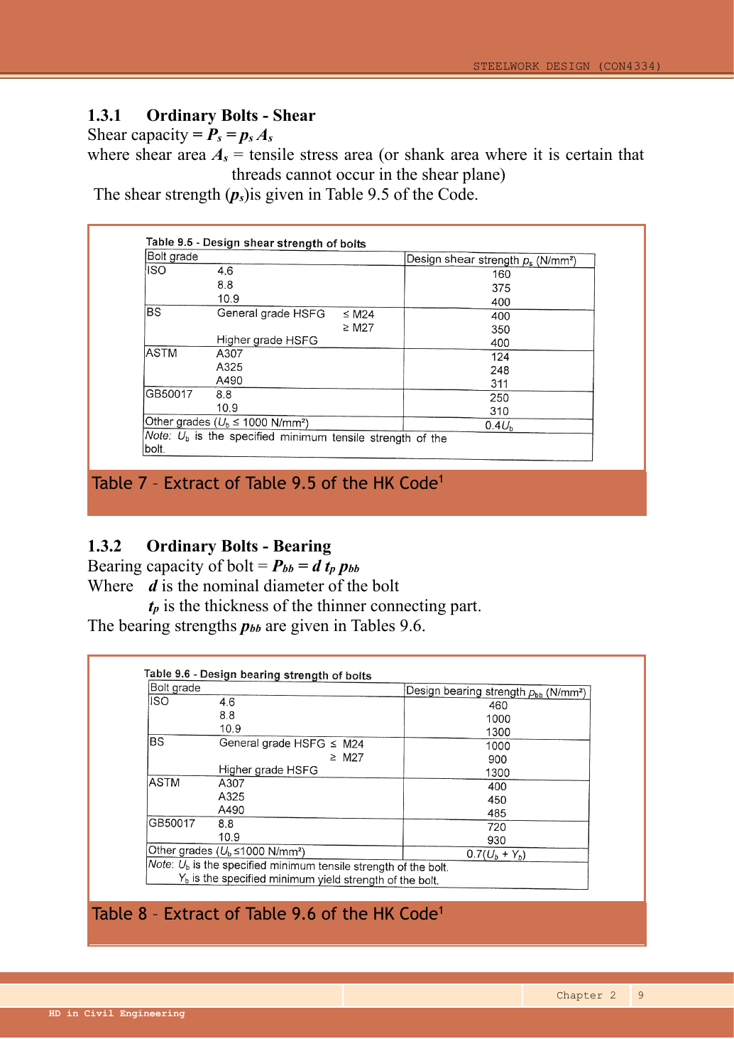
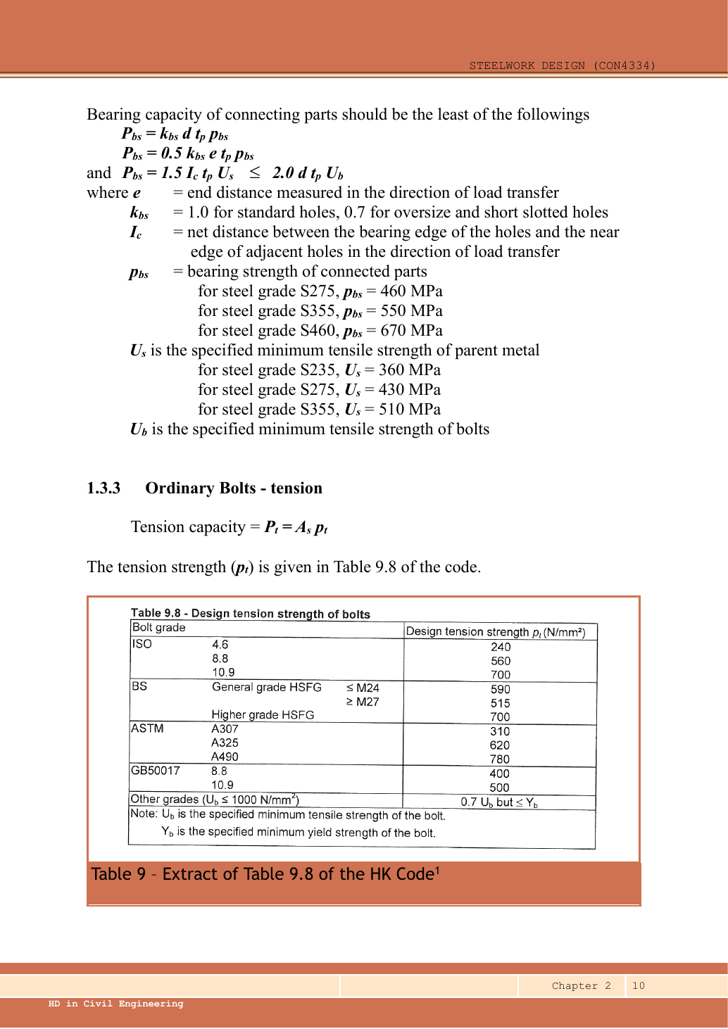
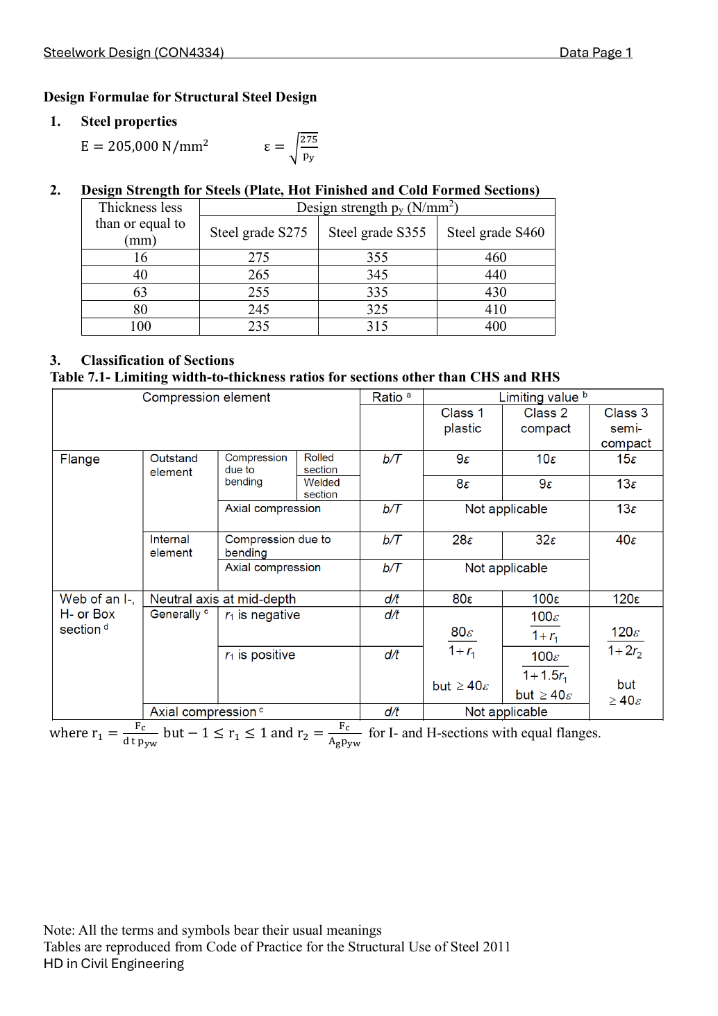
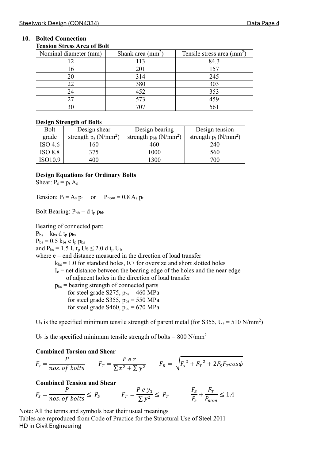
Grade 8.8: shear strength ps = 375, bolt bearing pbb = 1000, ultimate bolt strength Ub = 800 N/mm².
S355 plate: pbs = 550, Us = 510 N/mm², Ke = 1.1.
Use threaded stress area As for the conservative shear plane, nominal d for bearing, and hole diameter d0 for material removed.
The two symmetric side plates share the total force and moment equally.
Work on ONE plate, using bolt coordinates measured from that plate’s bolt-group centroid.
A bolt connecting this side plate to its column flange is in single shear.
Result and concise exam wording — key result lines
The two symmetric side plates share the total force and moment equally.
Work on ONE plate, using bolt coordinates measured from that plate’s bolt-group centroid.
A bolt connecting this side plate to its column flange is in single shear.
Maximum bolt force [5 marks]
Use the same mechanism: Add force components at each bolt. At fixed force, increasing eccentricity increases the moment component. Its direction differs between bolts.
Apply the reasoning to this section’s data and conditions
Direct shear P/n acts equally on each bolt.
Torsion adds a force perpendicular to the radius.
At the most loaded corner, its vertical component adds to direct shear.
Calculate both components before the resultant.
Result and concise exam wording — key result lines
Direct shear P/n acts equally on each bolt.
Torsion adds a force perpendicular to the radius.
At the most loaded corner, its vertical component adds to direct shear.
Calculate both components before the resultant.
Bolt shear [2 marks]
Use the same mechanism: Count cuts through each loaded bolt. For equal sharing and unchanged bolt area, two active planes provide twice one plane’s shear resistance.
Apply the reasoning to this section’s data and conditions
FAIL
Result and concise exam wording — key result lines
FAIL
Bolt bearing [2 marks]
Use the same mechanism: Follow contact pressure into the plate. At fixed geometry and strength, a thicker plate raises plate resistance. Moving a hole too near the end can still govern.
Apply the reasoning to this section’s data and conditions
The column flange is another connected part.
Its actual thickness must also pass; compare the lower bolt-bearing resistance.
Result and concise exam wording — key result lines
The column flange is another connected part.
Its actual thickness must also pass; compare the lower bolt-bearing resistance.
Plate bearing [6 marks]
Use the same mechanism: Follow contact pressure into the plate. At fixed geometry and strength, a thicker plate raises plate resistance. Moving a hole too near the end can still govern.
Apply the reasoning to this section’s data and conditions
For the vector force, check distance to the edge and neighbouring hole in the bearing direction.
A conservative independent-component check uses each component divided by its directional resistance and requires their sum ≤ 1.
It bounds a linear interaction rather than pretending the resultant acts vertically.
Horizontal side-plate direction
Vertical side-plate direction
FAIL
Result and concise exam wording — key result lines
FAIL
Reusable procedure and common errors
Use the same mechanism: Count cuts through each loaded bolt. For equal sharing and unchanged bolt area, two active planes provide twice one plane’s shear resistance.
Use the same mechanism: The weld resists through its throat. At fixed weld strength, doubling the leg doubles throat and line resistance in this model. Detailing limits can prevent that choice.
Apply the reasoning to this section’s data and conditions
Draw the load-transfer stages.
Count bolts and shear planes for one stage, then compare all failure modes.
Resolve eccentric forces as vectors.
Never add perpendicular components arithmetically.
- Use effective weld length and check size limits after strength; “strong enough” does not fix an impossible detail.
Explained variant — invented example
Use the same mechanism: The weld resists through its throat. At fixed weld strength, doubling the leg doubles throat and line resistance in this model. Detailing limits can prevent that choice.
Change the ruler, keep the quantity
A section table uses centimetres, but the strength calculation uses millimetres. The numbers must describe the same section.
Prediction, then explanation. Would every property increase by ten? No. The exponent determines how many factors of ten are needed.
First identify the physical quantity. Next convert each length factor. Keep force and length conversions separate when converting a moment.
Here n is the length exponent: 2 for area, 3 for section modulus and 4 for second moment of area.
Scope. Changing units changes neither the load nor the section. A conversion factor cannot repair a formula for the wrong physical quantity.
Check and takeaway. Illustration: . The fourth power belongs to the unit, not the number 2.
Apply the reasoning to this section’s data and conditions
Invented variant: all applied loads are 10% larger but geometry is unchanged.
What scales, and what does not?
Hint
Isolate one load-transfer stage, then distinguish demand from fixed resistance.
Explained answer
For these linear elastic models, bolt forces and weld force per unit length rise 10%; required strength-only weld throat also rises 10%.
Bolt areas, section capacities, effective lengths of already specified welds and detailing limits stay unchanged.
Recheck every utilisation.