Steel and sections
Reading the section tables, taking the design strength from grade and thickness, and telling strength checks from deflection checks.
Read an I-section and its section table (Section Properties)
The wide top and bottom parts of an I-section are flanges; the thinner vertical plate between them is the web. Under the main bending direction used in this course, the flanges carry substantial compression and tension, while the web is important in transmitting shear. This is an intuitive starting point for the formulas, not a claim that the other parts carry no stress.
In the section table, is overall depth, is flange thickness and is web thickness. The effective web depth used for classification may differ from . is gross area. and are second moments of area, describing how material is distributed about an axis and influencing bending stiffness.
This course uses for plastic section modulus and for elastic section modulus. Other books may use different symbols; do not substitute them without checking. Identify the and axes from the section-table sketch rather than guessing their directions from the letters.
A designation such as 406×140×46 UB gives nominal dimensions; the last number is mass per metre. Read actual , , , , and from that section's table row. Nominal dimensions are not substitutes for every calculation dimension.
| Symbol / Unit | Meaning |
|---|---|
| Second moment of area, mm⁴ | |
| , | Section modulus, mm³ |
| Radius of gyration, mm |
Steel grades S275, S355 and S460, and strength classification
A question that says Grade S355 is giving the steel grade. Grades are named under the British Standard BS EN 10025: the first letter of S355 stands for structural steel, and the number 355 is the nominal strength in N/mm². Chapter 1 of the lecture notes lists S275, S355 and S460 as the common grades, with nominal strengths of 275, 355 and 460 N/mm².
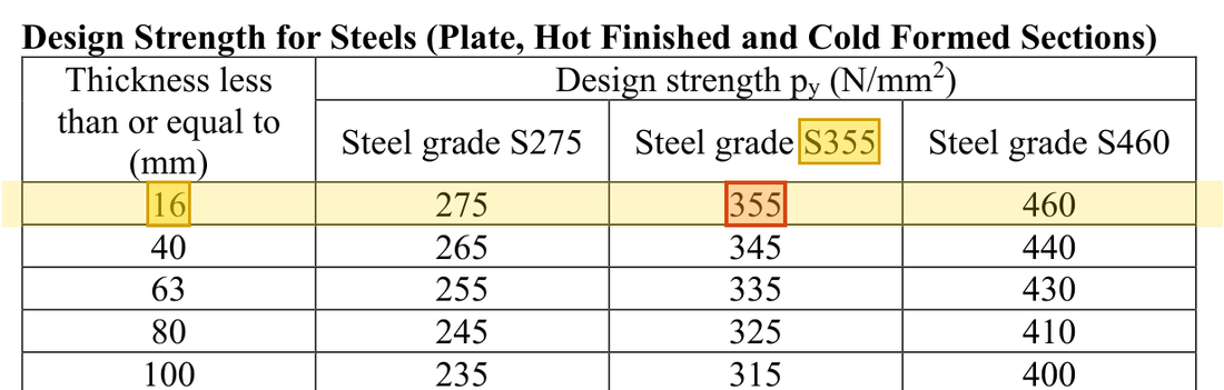
Grades are set by the steel's minimum yield strength: S355 steel up to 16 mm thick has a yield strength of at least 355 N/mm², which the steel mill proves with tensile tests. The designer specifies the grade on the drawings and in the specification, so you do not decide it in a calculation. Every worked example in this course states Grade S355, so the first step is to find the grade in the question; after that, read only that grade's column in the Data File.
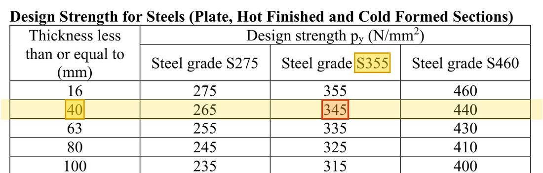
Within one grade, a thicker element has a lower design strength , so before reading you classify the strength: find the thickness that governs, then go down the table on Data File page 1 to the first row not less than that thickness (16, 40, 63, 80 or 100 mm). Where that row meets the grade's column is . The note under the table in the lecture notes says a rolled section is classified by the thickness of its thickest element.
Which thickness to use: in an I-section such as a UB or UC the flange is thicker than the web, so use the flange thickness ; for a plate use the plate thickness; for an angle use the leg thickness. A thickness exactly on a limit stays in that row, so belongs to the 16 mm row. In one joint, elements of different thickness can have different , for example 345 N/mm² for a 22 mm main plate and 355 N/mm² for a 12 mm cover plate.
Some values depend on the grade only, not on thickness: for S355 plate the bearing strength , the ultimate tensile strength , the effective net area coefficient , and, with class 42 electrodes, the fillet weld strength . If a question uses S275 instead, read all of these from the S275 entries (, , ).
Bolt Grade 8.8 is a separate classification, not a steel grade like S275 or S355. The first 8 means an ultimate tensile strength ; the second 8 means the yield strength is about 0.8 times the tensile strength. In the bolt tables use the Grade 8.8 row (, , ), not the plate grade's values.
Section classification into Class 1 to 4 is something else again: it compares the width-to-thickness ratios of the flange and web to judge local buckling. Its limits use , so the order is to read from the grade and thickness first, then classify the section.
| Member in this course | Thickness used | Table row | (S355) |
|---|---|---|---|
| 406×140×46 UB (floor beam B1) | Flange | ≤16 mm | 355 N/mm² |
| 457×191×82 UB (8 m revision beam) | Flange | ≤16 mm (exactly on the limit) | 355 N/mm² |
| 254×254×89 UC (Example 5 column) | Flange | ≤40 mm | 345 N/mm² |
| 305×305×198 UC (column Q3) | Flange | ≤40 mm | 345 N/mm² |
| 80×60×8 angle (M20 bolt example) | Leg 8 mm thick | ≤16 mm | 355 N/mm² |
| Main plate of the double-cover splice | Plate 22 mm thick | ≤40 mm | 345 N/mm² |
| Cover plates of the double-cover splice | Plate 12 mm thick | ≤16 mm | 355 N/mm² |
| Symbol / Unit | Meaning |
|---|---|
| Design strength, read from the grade and the thickness of the thickest element, N/mm² | |
| Flange thickness; a UB or UC is strength-classified by it, mm | |
| Ultimate tensile strength of the plate, read from the grade only, N/mm² | |
| Ultimate tensile strength of the bolt, 800 N/mm² for Grade 8.8 |
When to check strength and when to check deformation (Limit States)
The ultimate limit state (ULS) concerns unacceptable failure such as loss of load capacity or instability. The serviceability limit state (SLS) concerns deformation, vibration and damage to finishes during normal use. A beam may be strong enough but still deflect too much.
Dead or permanent load includes self-weight and fixed installations. Imposed or live load arises from use and occupancy. The course examples commonly use for ULS. The factors 1.4 and 1.6 belong to the course's design combination; they are not unit conversions, and are not replaced here with values from another code.
Some course deflection problems use only unfactored imposed load. Before calculating, write two lists: the loads and factors used for ULS, and the load whose deformation is checked at SLS. Do not factor a load already labelled ultimate again.
| Symbol / Unit | Meaning |
|---|---|
| Unfactored permanent load | |
| Unfactored imposed load | |
| ULS/SLS | Different design limit states |
Will the plate buckle before its material strength is fully mobilised? (Section Classification)
Local buckling is instability of an individual thin compression plate within the section. It differs from a whole column bending sideways. Wide, thin flanges or webs are more susceptible, so width-to-thickness ratios must be checked.
Classes 1, 2, 3 and 4 in this course describe a section's ability to achieve and sustain the relevant elastic or plastic behaviour. Classification determines which bending resistance expression may be used. Classify first, then calculate capacity; do not assume is always available.
Obtain for the steel grade and thickness, then calculate . Select the correct plate element, manufacturing method, support boundaries and compression condition in the table. Compare actual or with the corresponding multiples of . Check both flanges and web; the less favourable class governs the whole section.
| Symbol / Unit | Meaning |
|---|---|
| Relevant flange width-to-thickness ratio | |
| Relevant web width-to-thickness ratio | |
| Strength adjustment factor in the course classification table |
Excessive bending deformation versus insufficient resistance (Deflection)
Deflection is a member's displacement from its original position, commonly measured in mm. Excessive deflection during normal use can damage brittle finishes or impair use. SLS can therefore fail even before the material yields.
is flexural rigidity. describes the material's elastic response; describes the distribution of material in the section. For unchanged loading and span , a larger gives less deflection . Capacity and stiffness are different concepts: cannot replace .
The course uses 5wL⁴/(384EI) for a simply supported beam under full-span UDL, and for a central point load. Treat any additional loads using their corresponding models. Choose , or according to the course's use and loading conditions; you cannot simply choose the most permissive limit.
| Symbol / Unit | Meaning |
|---|---|
| Deflection, mm | |
| 205000 N/mm² in this course | |
| Second moment of area about the bending axis, mm⁴ |