Tutorial 3 Q2: fully restrained floor beams, including local web checks
Open “Animation lab” beside a teaching step for a visual explanation or a walkthrough of its original expressions. Models are illustrative; source answers remain unchanged.
Need a simpler picture? Open “Simple explanation” beside a difficult step. These optional notes do not replace the full solution.
Check B1, B2 and B3 for bending, shear and imposed-load deflection with brittle finishes. Also check B3 support web bearing and web buckling with the given stiff bearing and local restraints.
Original source: LectureNotes/Ch 3_Beam.pdf — p. 35, p. 36. Values tagged given are in the question or diagram; lookup values come from a named table; calculated values follow from the working; assumptions are stated explicitly.
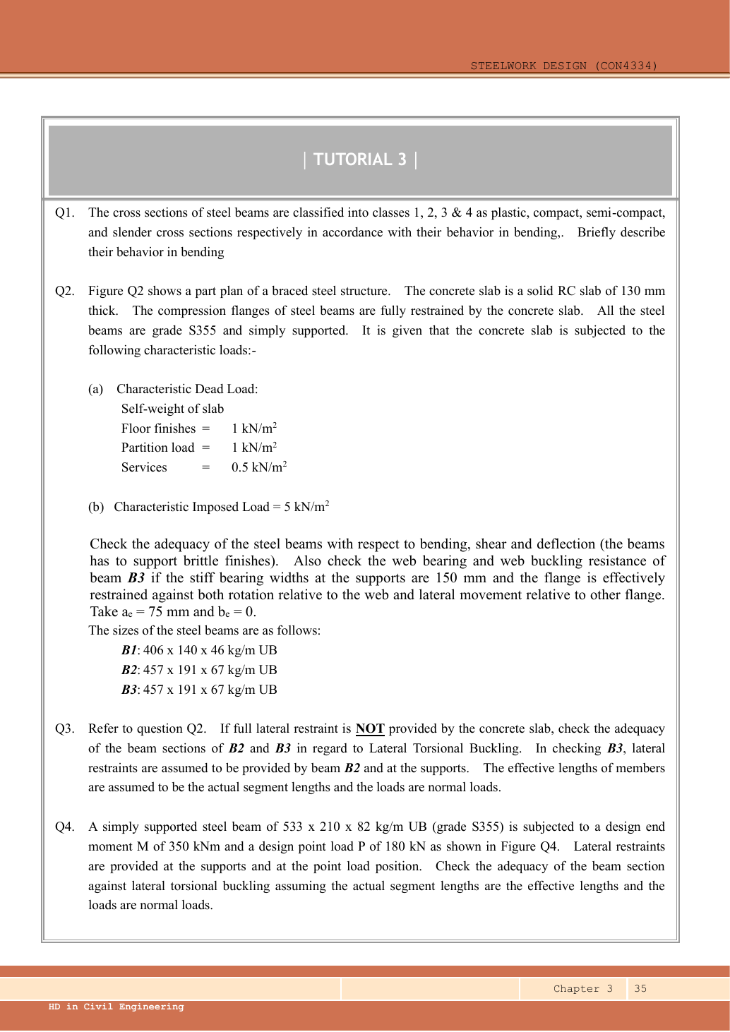
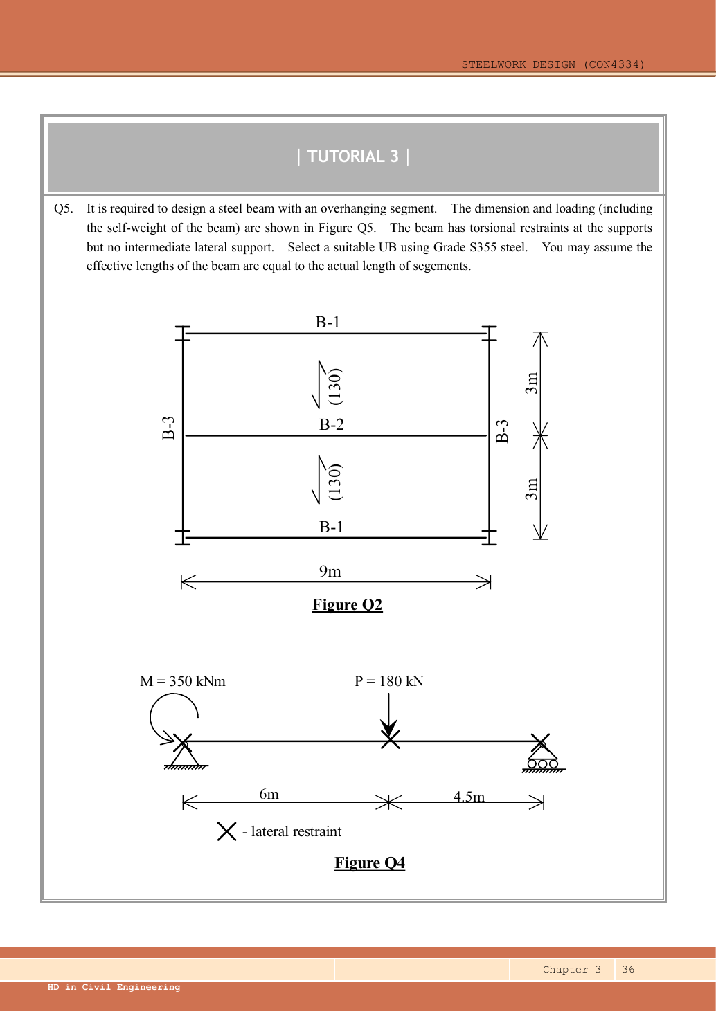
Read the diagram and collect the data
| Given or adopted input | Exact origin |
|---|---|
| Floor geometry | FigureQ2: each horizontal B1/B2 spans ; vertical B3 spans . Slab spans vertically between horizontal beams. |
| Tributary widths | Top/bottom B1 takes half of one slab bay=. Middle B2 takes from each side=. |
| Slab thickness | The parenthesised in each slab bay denotes RC slab; it is not a load intensity. |
| Surface loads | Q2 text: finishes , partitions , services , imposed , all . |
| Members | B1 UB; B2 and B3 UB; S355, simple supports and full compression-flange restraint for Q2. |
| Additional B3 support data | Stiff bearing , aₑ75 mm, bₑ0; both local flange restraints explicitly given. |
| Table mass for self-weight | kg/m and from Data File p.9; multiply by the assumed for this numerical demonstration. |
Keep (concrete unit weight, ) and (acceleration, ) symbolic until supplied. These equations are the source-supported general solution for the missing inputs:
Before calculating: recognition and strategy
Follow load paths before choosing formulas. Both B1 and B2 carry a floor UDL; B3 receives the central B2 end reaction plus its own weight. B1 end reactions are located at B3’s supports, so they increase column/joint reactions but not B3’s span bending. Full slab restraint suppresses LTB for Q2, but not shear, deflection or local web failure.
1. Convert slab thickness and collect surface loads
Simple explanation: How a floor load reaches a beam
Each beam collects the load from its own strip of floor.
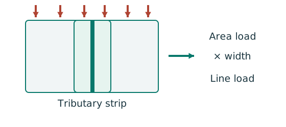
- Find the tributary width from the actual plan.
- Area load × tributary width gives load per beam length.
- A supporting beam receives the other beam’s end reaction.
Remember: A reaction becomes a point load, not automatically a UDL.
Self-weight is a dead load, so its factor is applied in the next lines. The imposed-only serviceability calculation does not use either strength factor.
Animation labFrom characteristic to design load
Supplement to the original lesson. Enable JavaScript to play, step through calculations and rotate 3D models. The following explanation remains readable offline.
- G is permanent load; Q is imposed load. A surface load and a line load also have different units.
- This illustration uses the course gravity case . Other combinations in the original text retain their own factors.
- For illustrative , change Q and watch each separate contribution.
- Do not carry this ULS total automatically into deflection. Follow the stated SLS load case.
2. Edge beam B1: loads, actions, section and deflection
Simple explanation: Strong enough and stiff enough are two questions
A shelf can avoid breaking yet still sag too much.
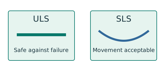
- ULS checks safety against the relevant failure modes.
- SLS checks the specified everyday-use limit.
- Use the load case required for each check.
Remember: Passing bending resistance does not prove deflection passes.
Lookup: Data File pp.9–10, exact UB row. Dimensions on p.9; properties on p.10. is overall depth; is the clear web depth between root fillets, not the nominal designation.
| Property | Lookup value / conversion |
|---|---|
| Dimensions | D403.2, web t 6.8, flange T11.2, root r 10.2, clear d 360.4, all |
| Local ratios | ;。 |
| Major-axis properties | ; ; . |
| LTB properties | ; ; torsional index . |
Deflection uses imposed UDL , , and . The simply supported UDL formula follows by integrating the curvature and relationship with zero displacement at both supports.
Animation labFollow the floor load in 3D
Supplement to the original lesson. Enable JavaScript to play, step through calculations and rotate 3D models. The following explanation remains readable offline.
- The floor carries pressure in . The highlighted strip belongs to one secondary beam.
- Multiply pressure by tributary width: . The illustration uses .
- A primary beam receives the secondary beam reaction at their connection, not a new full-span UDL.
- Trace reactions down to columns and foundations. Count each loaded area once.
3. Interior beam B2: twice the floor tributary width
Lookup: Data File pp.9–10, exact UB row. Dimensions on p.9; properties on p.10. is overall depth; is the clear web depth between root fillets, not the nominal designation.
| Property | Lookup value / conversion |
|---|---|
| Dimensions | D453.4, web t 8.5, flange T12.7, root r 10.2, clear d 407.6, all |
| Local ratios | ;。 |
| Major-axis properties | ; ; . |
| LTB properties | ; ; torsional index . |
Each B3 receives one half of B2’s whole load. Do not use its ultimate reaction in an imposed-only deflection calculation.
Animation labFollow the floor load in 3D
Supplement to the original lesson. Enable JavaScript to play, step through calculations and rotate 3D models. The following explanation remains readable offline.
- The floor carries pressure in . The highlighted strip belongs to one secondary beam.
- Multiply pressure by tributary width: . The illustration uses .
- A primary beam receives the secondary beam reaction at their connection, not a new full-span UDL.
- Trace reactions down to columns and foundations. Count each loaded area once.
4. Supporting beam B3: one midpoint reaction plus self-weight
B3 has the same section as B2, so the already demonstrated Class 1 and no-shear-buckling results apply. At each corner the column additionally receives B1’s end reaction; that load at a support does not create span moment in B3.
The midspan point-load expression contains . The point-load expression printed on Data File p.2, , is dimensionally incorrect; the course example uses . gives .
Animation labFollow the floor load in 3D
Supplement to the original lesson. Enable JavaScript to play, step through calculations and rotate 3D models. The following explanation remains readable offline.
- The floor carries pressure in . The highlighted strip belongs to one secondary beam.
- Multiply pressure by tributary width: . The illustration uses .
- A primary beam receives the secondary beam reaction at their connection, not a new full-span UDL.
- Trace reactions down to columns and foundations. Count each loaded area once.
5. B3 support web bearing
Simple explanation: A concentrated force can hurt one small region
A narrow contact presses much harder locally than the same force spread over a wider contact.
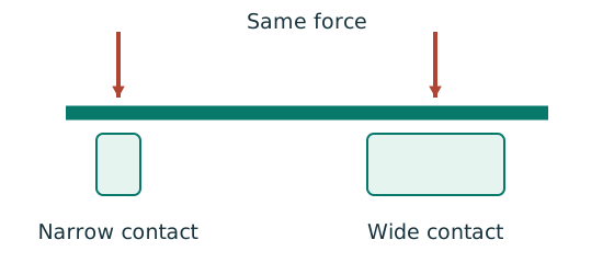
- Find the actual stiff bearing length and end position.
- Check local crushing and local web buckling separately.
- Use the restraint conditions required by each expression.
Remember: Missing contact dimensions cannot be guessed from drawing scale.
The question supplies stiff bearing, and . At an end bearing, the course dispersal factor is . is the flange-plus-root distance. The local load is the B3 span reaction under this model.
The B1/column corner load-transfer detail is not shown. If the B1 reaction also enters the same B3 web-bearing zone, a conservative demand is . This alternative demand is also below the bearing and buckling resistances below. Do not invent a different actual bearing detail.
Animation labSpread a concentrated force into the web
Supplement to the original lesson. Enable JavaScript to play, step through calculations and rotate 3D models. The following explanation remains readable offline.
- A concentrated reaction first enters through the bearing/contact region.
- The flange and root geometry spread the force before it enters the web.
- A wider effective bearing region can reduce local stress for the same force.
- End distance, stiff bearing length and restraint conditions must come from the original question. This slider is illustrative only.
6. B3 support web buckling and conclusion
Simple explanation: What to do when one input is missing
A calculator cannot supply a dimension that the drawing never gave.
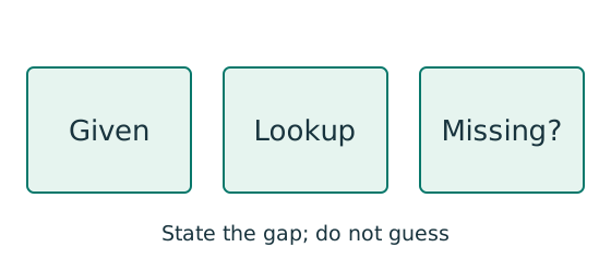
- Separate given values, table values and calculated values.
- Complete the checks whose required inputs are available.
- State the missing input beside the remaining conditional result.
Remember: An illustrative assumption must not become an unstated exam given.
Both local flange restraints specified in the question are present, so no additional reduction is needed. is below 246.986831; even the conservative combined corner demand is below it. All requested Q2 beam checks pass for the explicitly adopted loading constants.
Animation labThe web behaves like a short strut
Supplement to the original lesson. Enable JavaScript to play, step through calculations and rotate 3D models. The following explanation remains readable offline.
- A concentrated force compresses a local region between the flanges.
- The thin web can buckle sideways before local crushing governs.
- The source distinguishes restraint against rotation and relative lateral movement.
- Web bearing and web buckling are separate checks. Select the original expression whose assumptions are satisfied.
Compact exam answer
| Beam | Ultimate / | Imposed / limit | Result |
|---|---|---|---|
| / | / | Pass | |
| / | / | Pass | |
| / | / | Pass |
, ; including tabulated beam weight and using . Section is Class 1. B3: , , with local restraint given. Full slab restraint means Q2 requires no LTB check.
Mistakes to avoid
- The dimension is the B1/B2 span, not B3’s span.
- B2 receives tributary width; B1 receives .
- Do not apply ULS factors in imposed-load deflection.
- Use for a central point, for a UDL.
Procedure for an unfamiliar variant
- Read slab direction, tributary widths, beam spans and restraint positions from the source.
- Separate characteristic dead/imposed loads; factor only strength loads.
- Pass a supporting beam the reaction from the supported beam, not its full load.
- Draw the beam free body, solve reactions and obtain shear/moment ordinates.
- Read the exact section row, classify and check shear before selecting the bending formula.
- Check imposed-load deflection with consistent and .
- Where requested, check bearing/web buckling and each unrestrained segment independently.
Independent self-check
Try it yourself. Invented variant: imposed surface load rises from to . Which beam first fails its brittle-finish deflection limit?
Reveal answer and reasoning
Deflection increases linearly with imposed load. B1: ; B2: , fails. B3: . Ultimate loads have changed; strength checks must be recalculated separately.
Animation labSee stiffness and deflection
Supplement to the original lesson. Enable JavaScript to play, step through calculations and rotate 3D models. The following explanation remains readable offline.
- Use the specified SLS load, span and support arrangement. The demonstrator has a full-span UDL.
- The loaded beam bends; the deformation is exaggerated so its shape can be seen.
- For a simply supported full-span UDL, . Double L with w, E and I unchanged: δ becomes 16 times as large.
- The readout uses , and . Select the finish/support-specific limit from the original table.