Steelwork · Exam learning

2022–2024 · Exam-focused route

2023 FT/PTD BQ2(a) — double bolted angles Section B · choose 2 of 3

Solve all four strength checks; distinguish angle-pair action from a single-angle example.

Original source: 22ENGTY006.pdf · physical page 3

Note: marks are as printed in the paper; the working is a teaching guide, not an official marking scheme.

Read the double-angle connection

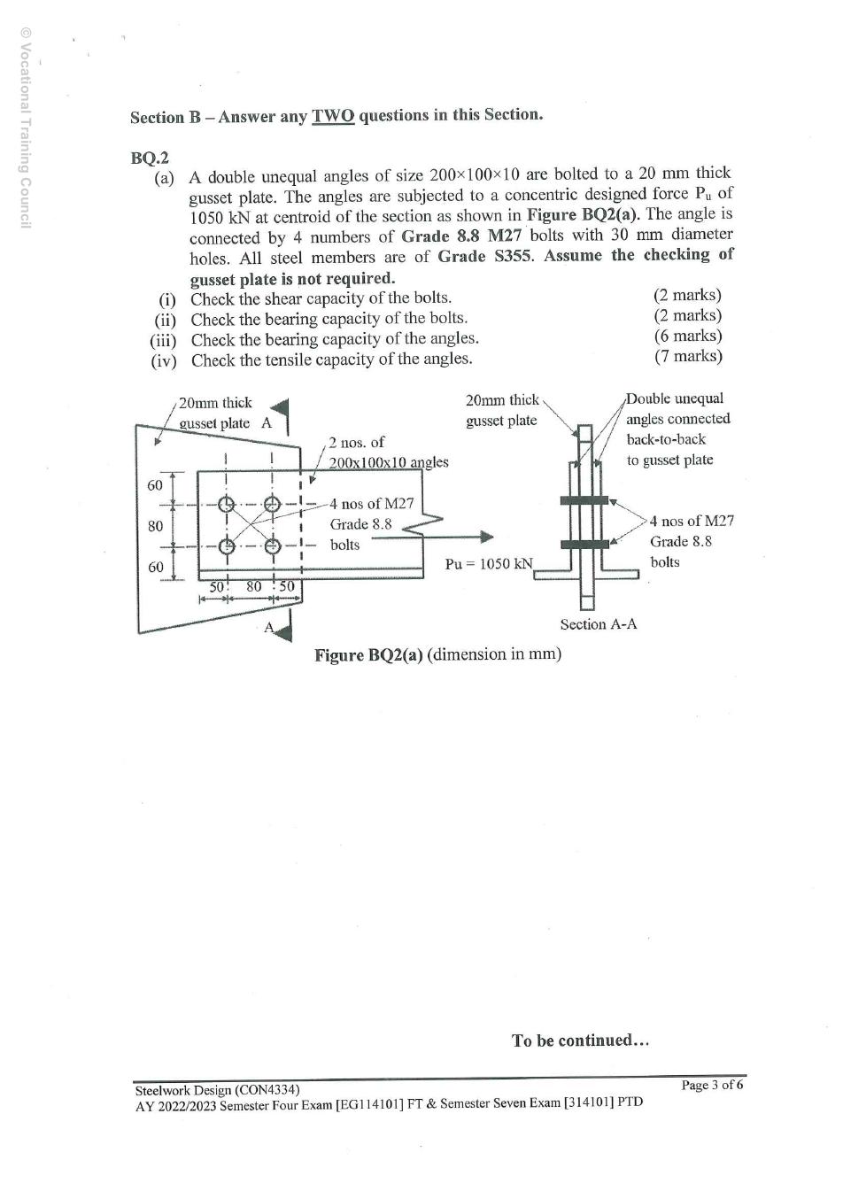
Given: two 200 × 100 × 10 unequal angles, one each side of a 20 mm gusset; four M27 Grade 8.8 bolts in 30 mm holes; S355; 1,050 kN concentric ultimate tension. Gusset strength is explicitly excluded. The front view has two longitudinal columns at 80 mm pitch, 50 mm end distance, and two transverse rows at 80 mm gauge with 60 mm edge distances. Section A–A confirms two shear interfaces, not eight physical bolts.

Source: LectureNotes/CON4334-Data File-20260730.pdf · p.4
Source: LectureNotes/Ch2_Connection.pdf · p.10, p.11, p.14, p.17

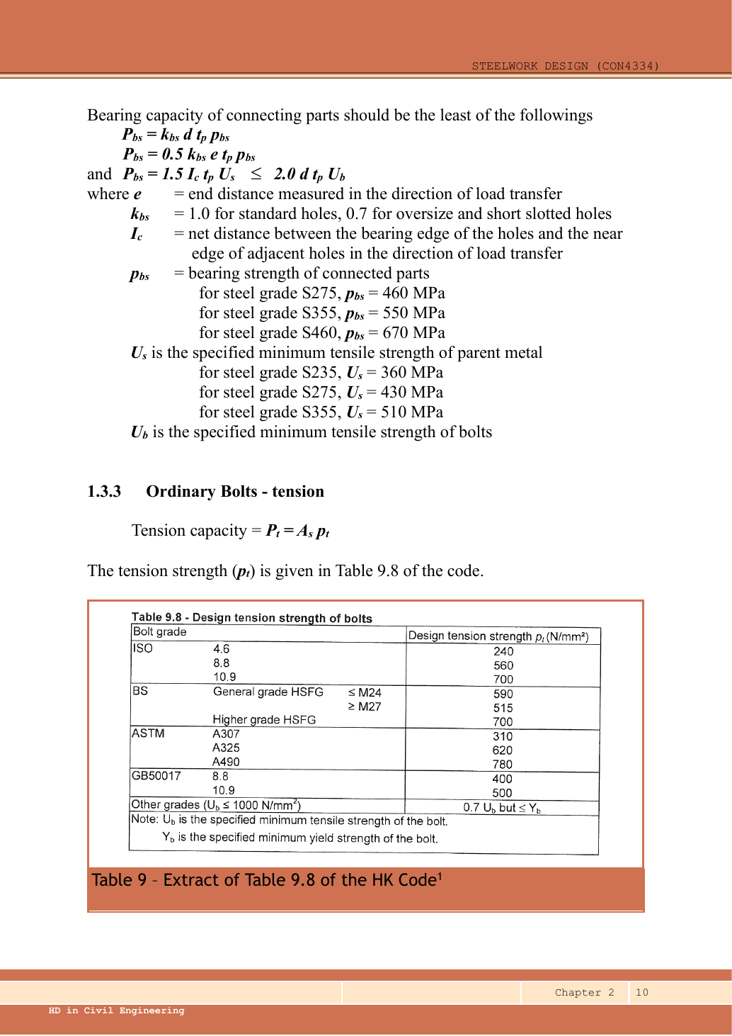
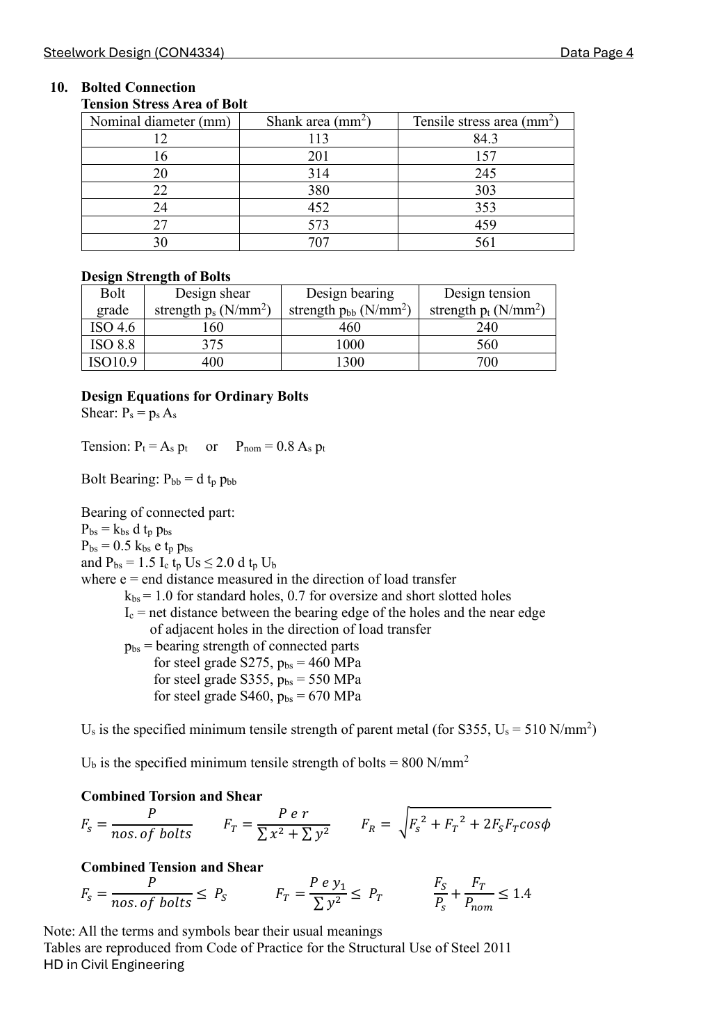
Lookups: Data File p.4, M27 tensile-stress-area row and ISO 8.8 strength row. Use thread area conservatively because a thread-free shear plane is not specified. For S355 plate bearing use 550 N/mm² and ultimate parent-metal strength 510 N/mm²; bolt ultimate strength is 800 N/mm². Ordinary 30 mm holes for M27 give the standard-hole factor one.

d=27 mm, d0=30 mm, As=459 mm2, kbs=1, Ke=1.1d=27\,\mathrm{mm},\ d_0=30\,\mathrm{mm},\ A_s=459\,\mathrm{mm^2},\ k_{bs}=1,\ K_e=1.1
ps=375,pbb=1000,pbs=550,Us=510,Ub=800[N/mm2]p_s=375,\quad p_{bb}=1000,\quad p_{bs}=550,\quad U_s=510,\quad U_b=800\quad[\mathrm{N/mm^2}]

Symbols: d is bolt diameter; d₀ hole diameter; Aₛ bolt stress area; pₛ shear strength; pbb bolt bearing strength; pbs connected-part bearing strength; Ke net-area coefficient. Subtract d₀ from metal width, but use d in bearing resistance. Stress × mm² gives N; divide by 1,000 for kN.

Simple explanation — open only if needed

Each angle pulls with half the total load. A bolt passes through angle–gusset–angle and can shear at both interfaces. The net angle section cuts across the two transverse bolt rows, so two holes are removed from each connected leg.

BQ2(a)(i) — double-shear bolts [2 marks]

Pangle=1050/2=525 kNP_{angle}=1050/2=525\,\mathrm{kN}
Ps,one=2(459)(375)/1000=344.25 kNP_{s,one}=2(459)(375)/1000=344.25\,\mathrm{kN}
Ps,group=4(344.25)=1377 kN>1050 kNP_{s,group}=4(344.25)=1377\,\mathrm{kN}>1050\,\mathrm{kN}

BQ2(a)(ii) — bolt bearing [2 marks]

tp=min⁡(20,10+10)=20 mmt_p=\min(20,10+10)=20\,\mathrm{mm}
Pbb,group=4(27)(20)(1000)/1000=2160 kN>1050 kNP_{bb,group}=4(27)(20)(1000)/1000=2160\,\mathrm{kN}>1050\,\mathrm{kN}

This checks bolt bearing against the total load. It does not reintroduce the excluded gusset-plate strength calculation.

BQ2(a)(iii) — angle bearing [6 marks]

The end distance is measured parallel to the force, from the free end to the nearest bolt centre. The clear inter-hole ligament is pitch minus one hole diameter. Use the smallest applicable bound; using the end-bolt bound for every bolt is conservative for the interior bolts.

t=10 mm, e=50 mm, p=80 mm, lc=p−d0=80−30=50 mmt=10\,\mathrm{mm},\ e=50\,\mathrm{mm},\ p=80\,\mathrm{mm},\ l_c=p-d_0=80-30=50\,\mathrm{mm}
B1=kbsdtpbs1000=1(27)(10)(550)1000=148.5 kNB_1=\frac{k_{bs}dtp_{bs}}{1000}=\frac{1(27)(10)(550)}{1000}=148.5\,\mathrm{kN}
B2=0.5kbsetpbs1000=0.5(1)(50)(10)(550)1000=137.5 kNB_2=\frac{0.5k_{bs}etp_{bs}}{1000}=\frac{0.5(1)(50)(10)(550)}{1000}=137.5\,\mathrm{kN}
B3=1.5lctUs1000=1.5(50)(10)(510)1000=382.5 kNB_3=\frac{1.5l_ctU_s}{1000}=\frac{1.5(50)(10)(510)}{1000}=382.5\,\mathrm{kN}
B4=2dtUb1000=2(27)(10)(800)1000=432 kNB_4=\frac{2dtU_b}{1000}=\frac{2(27)(10)(800)}{1000}=432\,\mathrm{kN}
Pbs,one=min⁡(B1,B2,B3,B4)=137.5 kNP_{bs,one}=\min(B_1,B_2,B_3,B_4)=137.5\,\mathrm{kN}
Pbs,one angle=4(137.5)=550 kN>525 kNP_{bs,one\ angle}=4(137.5)=550\,\mathrm{kN}>525\,\mathrm{kN}
Pbs,two angles=1100 kN>1050 kNP_{bs,two\ angles}=1100\,\mathrm{kN}>1050\,\mathrm{kN}

BQ2(a)(iv) — double-angle tension [7 marks]

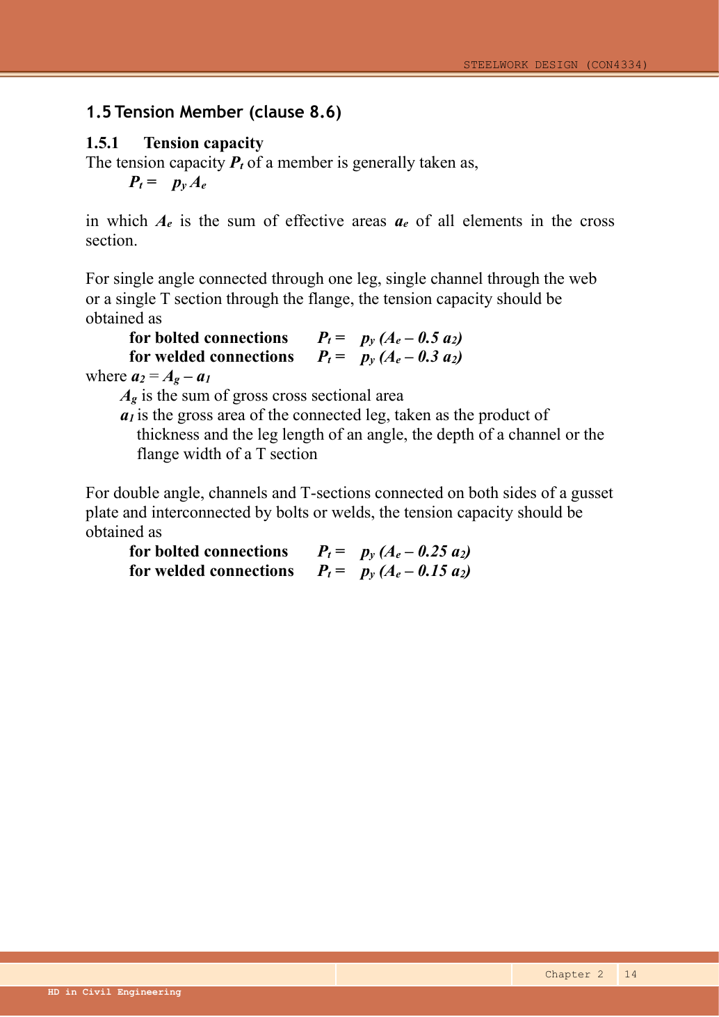
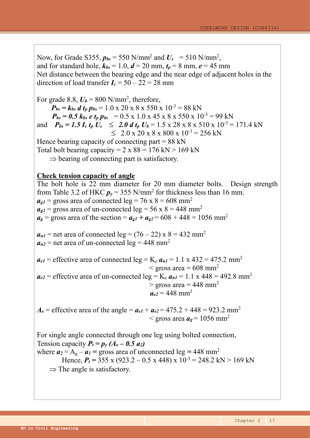
Follow the lecturer’s rectangular half-heel allocation (Chapter 2 example 1, p.17): allocate half the 10 mm heel to each leg. This avoids counting the corner twice. Ignore root radii consistently with that worked method. Compute one angle, then double its resistance.

b1=200−10/2=195 mm,b2=100−10/2=95 mmb_1=200-10/2=195\,\mathrm{mm},\quad b_2=100-10/2=95\,\mathrm{mm}
ag1=195(10)=1950 mm2,a2=ag2=95(10)=950 mm2a_{g1}=195(10)=1950\,\mathrm{mm^2},\quad a_2=a_{g2}=95(10)=950\,\mathrm{mm^2}
an1=(195−2(30))(10)=1350 mm2,an2=950 mm2a_{n1}=(195-2(30))(10)=1350\,\mathrm{mm^2},\quad a_{n2}=950\,\mathrm{mm^2}
ae1=min⁡(1.1(1350),1950)=1485 mm2a_{e1}=\min(1.1(1350),1950)=1485\,\mathrm{mm^2}
ae2=min⁡(1.1(950),950)=950 mm2,Ae=1485+950=2435 mm2a_{e2}=\min(1.1(950),950)=950\,\mathrm{mm^2},\quad A_e=1485+950=2435\,\mathrm{mm^2}

Chapter 2 p.14 uses the 0.25 outstanding-leg reduction for double bolted angles on opposite sides of a gusset. The single-angle 0.5 coefficient would be the wrong model. At 10 mm thickness S355 has design strength 355 N/mm².

Pt,one=py(Ae−0.25a2)/1000=355(2435−0.25(950))/1000=780.1125 kNP_{t,one}=p_y(A_e-0.25a_2)/1000=355(2435-0.25(950))/1000=780.1125\,\mathrm{kN}
Pt,pair=2(780.1125)=1560.225 kN>1050 kNP_{t,pair}=2(780.1125)=1560.225\,\mathrm{kN}>1050\,\mathrm{kN}

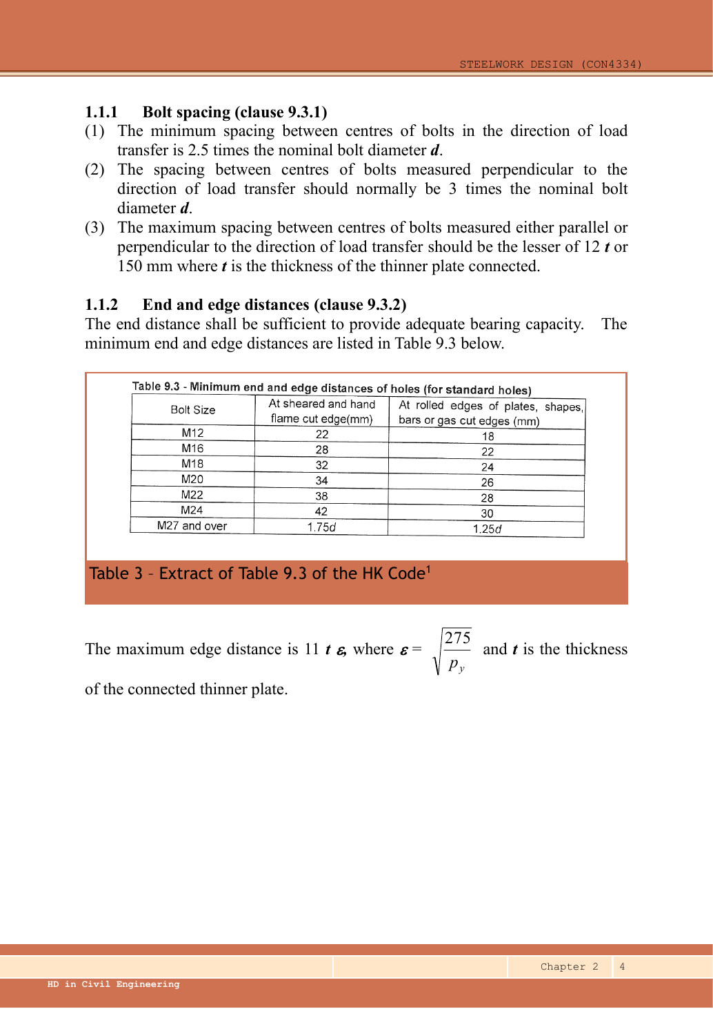
The four requested strength checks pass, with angle bearing governing at 1,100 kN. The drawn gauge is 80 mm whereas the course normal transverse spacing is 3d = 81 mm. Record this 1 mm detailing discrepancy; do not silently redraw it or claim a complete compliant layout.
Source: LectureNotes/Ch2_Connection.pdf · p.4

Compact exam script

Reveal the exam script
Ps=1377,Pbb=2160,Pbs,pair=1100,Pt,pair=1560.225[kN]P_s=1377,\quad P_{bb}=2160,\quad P_{bs,pair}=1100,\quad P_{t,pair}=1560.225\quad[\mathrm{kN}]

All exceed 1,050 kN; angle bearing governs. Exclude gusset strength as instructed and note the 80/81 mm gauge discrepancy.

Common mistakes

  • Four bolts in double shear is not eight bolts carrying separate groups of load.
  • A transverse fracture cuts two holes, not one and not four.

Procedure for a new variant

  1. Read the section view to count shear interfaces.
  2. Split load between identical angles, then check bolt and plate paths.
  3. Deduct holes on the actual transverse cut and use the double-angle coefficient.

Independent self-check — invented variant

Invented variant: increase load by 5%. Which mode decides adequacy?

Hint

Compare with the smallest resistance, not the largest.

Answer and reasoning
P=1.05(1050)=1102.5 kN>1100 kNP=1.05(1050)=1102.5\,\mathrm{kN}>1100\,\mathrm{kN}

Angle bearing now fails, despite bolt shear and angle tension still passing.