2022–2024 · Exam-focused route
2022 AQ1 — floor beams and fire protection Section A · compulsory
A complete 40-mark compulsory question. The highest-value habit is tracing which beam receives each slab strip and reaction.
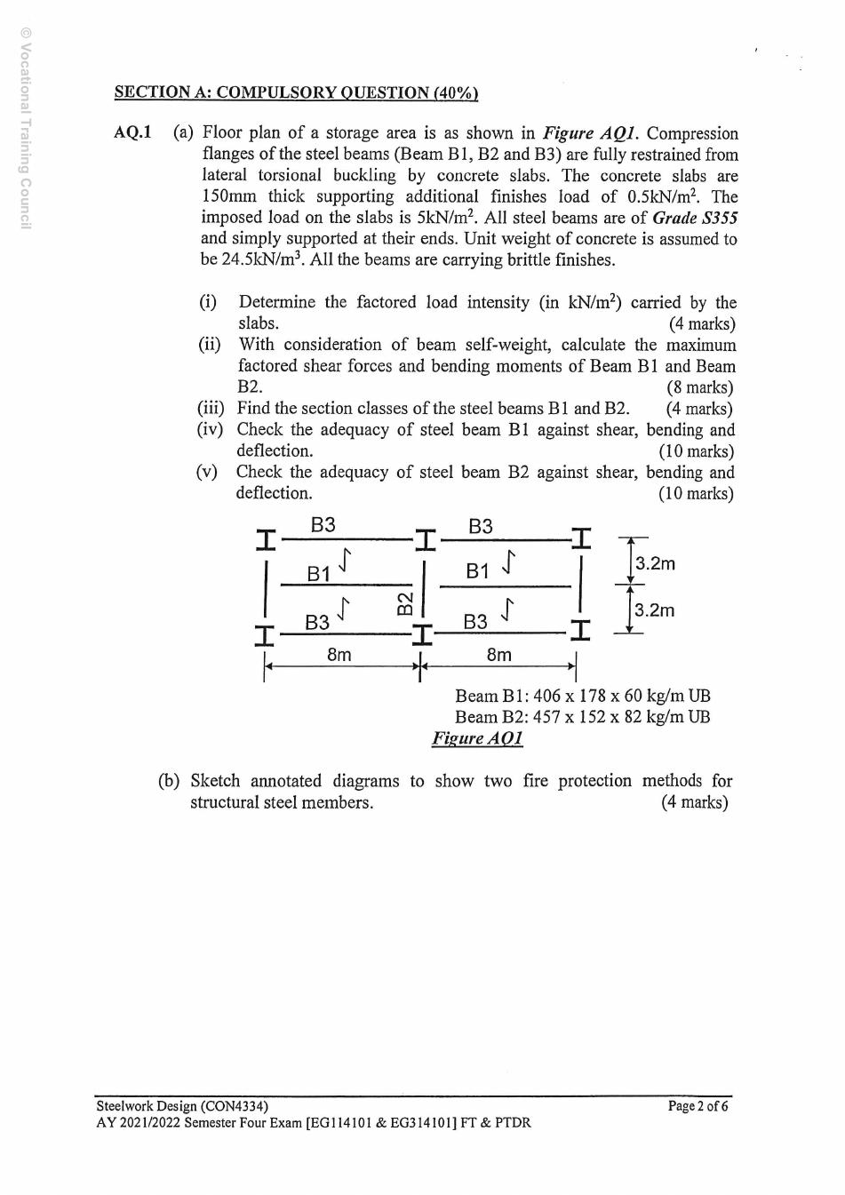
Note: marks are as printed in the paper; the working is a teaching guide, not an official marking scheme.
Read the load path before using a formula
Given: 150 mm slab, concrete unit weight 24.5 kN/m³, finishes 0.5 kN/m², imposed load 5 kN/m²; S355 beams, simple end supports, full slab restraint to the compression flange and brittle finishes. Find ULS actions, section classes, shear/bending resistance, imposed-load deflection, then sketch two fire-protection methods.
In the original plan, B1 spans 8 m. Its tributary width is 3.2 m: half the adjacent strip on each side. The central B2 span is 6.4 m, between the I-shaped column symbols. At its midpoint, TWO B1 members meet from opposite sides, so add their two end reactions. The slab load must not be applied to B2 a second time.
Simple explanation — open only if needed
Imagine the slab passing parcels to B1. Each B1 passes half its parcels to each support. The middle beam receives a parcel pile from each side, so the piles add. Its own weight is a separate load spread along its length.
Prerequisites: intensity × tributary width = line load; force × lever arm = moment. Use kN and metres for statics. Use N, mm and N/mm² for deflection and strength. One kN/m equals one N/mm. All intermediate values below are calculated without rounding until the displayed answer.
Collect the section data once
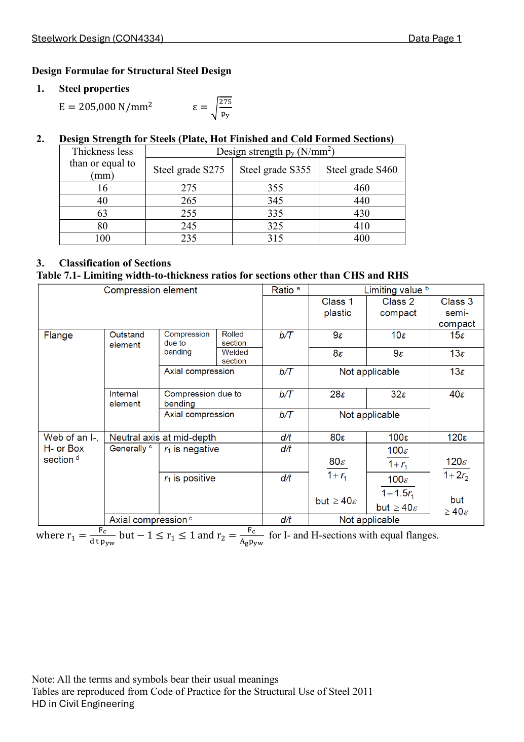
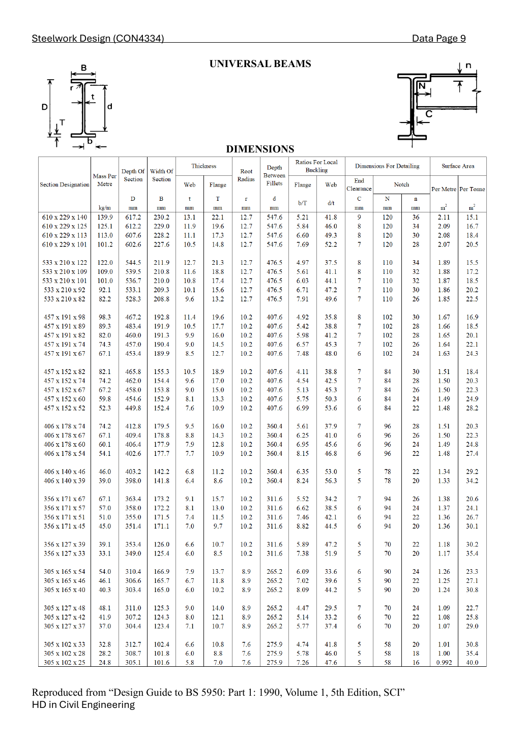
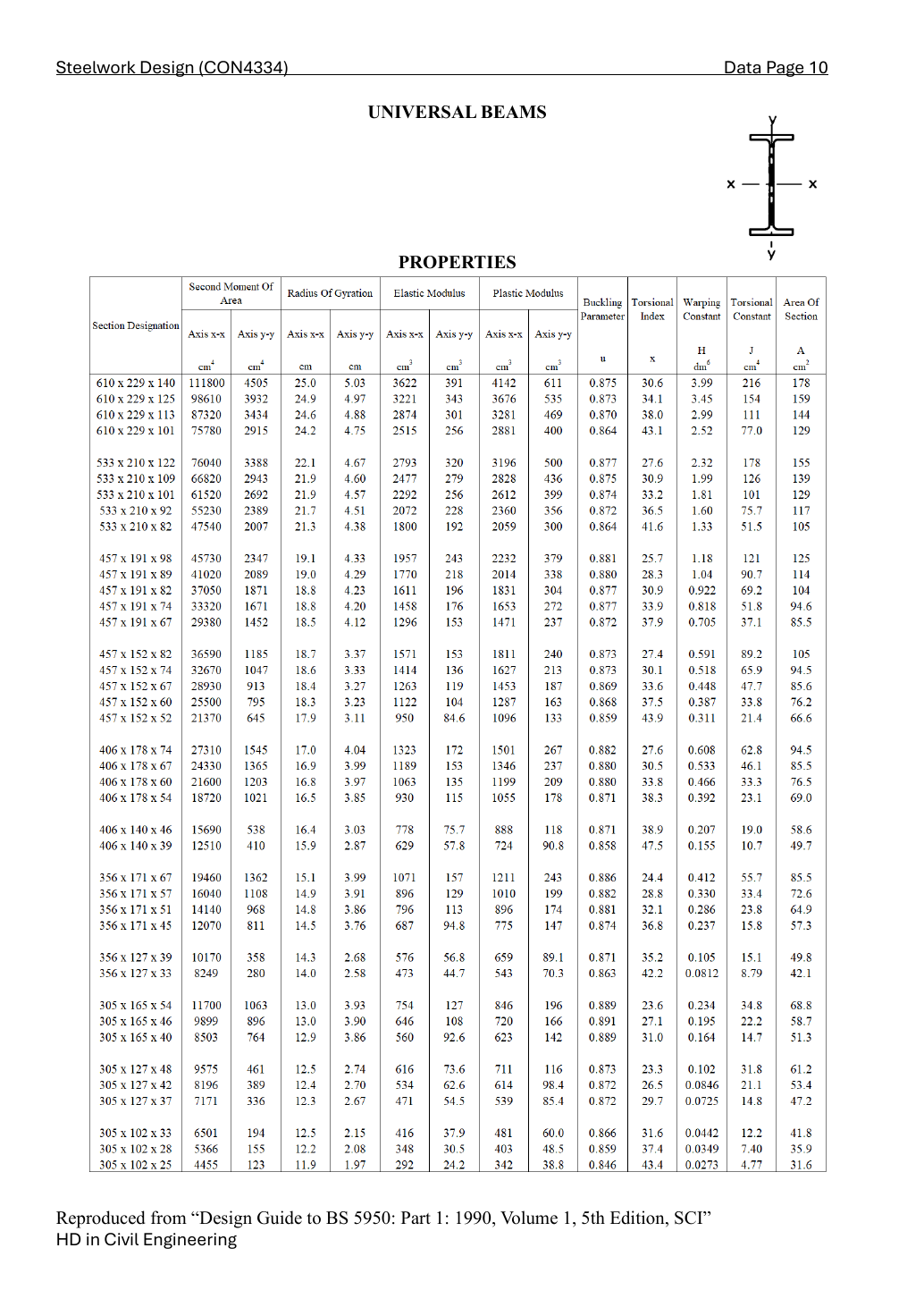
Look up the exact section designation, not the nearest depth. The mass column gives 60.1 and 82.1 kg/m; the rounded 60 and 82 in the names are labels. The flange thickness selects the design-strength row. E = 205,000 N/mm² is the course elastic modulus.
| Beam / section | Dimensions and ratios | Properties |
|---|---|---|
| B1 / 406 × 178 × 60 UB | ||
| B2 / 457 × 152 × 82 UB |
D is overall depth, t web thickness, T flange thickness, b flange outstand used by the table, d clear web depth, I second moment of area, Z elastic modulus and S plastic modulus. The table gives centimetre-based I, Z and S; convert explicitly below.
AQ1(a)(i) — slab design intensity [4 marks]
Convert slab thickness to metres before multiplying by concrete unit weight. Apply the course gravity ULS factors once to characteristic permanent and imposed loads.
AQ1(a)(ii) — actions on both beams [8 marks]
To turn the beam mass (kg/m) into a load (kN/m), use g = 10 m/s². The 2022 paper does not state g, so we use the usual course value; write “take g = 10 m/s²” in your answer. If a paper gives another g, only the self-weight terms change.
For a simply supported beam with uniform load, equilibrium shares the total load equally; the maximum sagging moment is at midspan.
B2 receives the two B1 reactions as ONE midspan point load. Add its own factored self-weight as a UDL; superpose the two standard simple-beam solutions.
Check: the two reactions of the supporting beam equal its point load plus its total self-weight. No extra slab UDL is added.
AQ1(a)(iii) — classification [4 marks]
Use the material strength selected by flange thickness. For a rolled I section in pure major-axis bending, Class 1 limits are 9ε for the compression-flange outstand and 80ε for the web. Both must pass. The web limit for uniform axial compression is different and must not be used here.
B1
B2
Both sections are Class 1, so the low-shear bending check may use the plastic modulus, subject to the elastic-modulus cap.
AQ1(a)(iv) — B1 adequacy [10 marks]
Shear is carried mainly by the web. The course rolled-I shear area is overall depth times web thickness. Multiply area by shear strength, then divide by 1,000 to obtain kN.
Shear passes and lies in the low-shear range, so no high-shear reduction is needed. Full slab restraint is given; this question needs section bending resistance, not an unrestrained-beam LTB calculation.
Deflection check (brittle finishes): use the unfactored imposed load only and the limit span/360. Do not apply the ULS load factors or add the beam’s own weight here.
All three requested checks pass under the stated load model.
AQ1(a)(v) — B2 adequacy [10 marks]
Shear is carried mainly by the web. The course rolled-I shear area is overall depth times web thickness. Multiply area by shear strength, then divide by 1,000 to obtain kN.
Shear passes and lies in the low-shear range, so no high-shear reduction is needed. Full slab restraint is given; this question needs section bending resistance, not an unrestrained-beam LTB calculation.
Deflection check (brittle finishes): use the unfactored imposed load only and the limit span/360. Do not apply the ULS load factors or add the beam’s own weight here.
All three requested checks pass under the stated load model.
AQ1(b) — two fire-protection methods [4 marks]
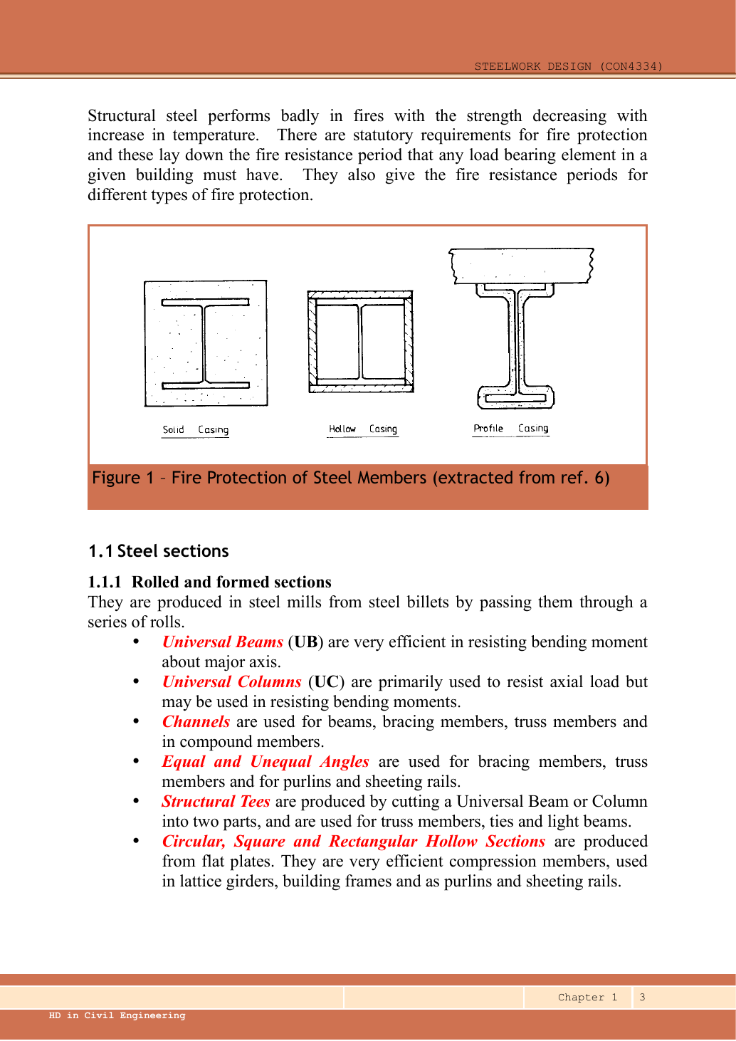
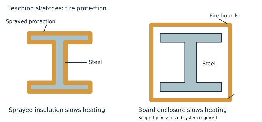
- Sprayed fire-resisting material: draw the I section with a continuous external insulation layer. Label steel, sprayed protection and exposure to fire. The layer slows heat transfer to steel so it retains useful strength for longer.
- Board encasement: draw a box around the I section, identify fire-resisting boards and their supports/joints. The enclosure delays heating. Do not claim a specific fire-resistance duration without a specified tested system.
For the full 4 marks: two methods, each with a labelled sketch and one sentence on how it slows down the heating of the steel.
Compact exam script
Reveal the exam script
Actions above are in kN and kN·m respectively. Both sections Class 1. B1: Pv 658.034 kN, Mc 425.645 kN·m, δ 19.271 mm < 22.222 mm. B2: Pv 974.198 kN, Mc 624.795 kN·m, δ 9.319 mm < 17.778 mm. Both pass. State g=10 and the two-reaction load path. For (b), give the two labelled sketches and explain delayed heating.
Common mistakes
- Do not use just one B1 reaction at the middle beam.
- Do not use ultimate loads in the imposed-load deflection check.
- Do not confuse cm⁴ with mm⁴: the conversion factor is 10,000.
Procedure for a new variant
- Trace slab → B1 → supporting beam → columns.
- Factor gravity loads, include each beam self-weight once, then solve statics.
- Classify, check shear range, bending and unfactored deflection.
Independent self-check — invented variant
Invented change: the middle beam receives only one B1 end reaction, with every other input unchanged. Which terms halve?
Hint
Separate the point-load solution from the self-weight UDL solution.
Answer and reasoning
Its B1 point-load contribution to shear, moment and live-load deflection halves. Its own-weight UDL contribution does not halve. B1 actions do not change. Recalculate by replacing the two-reaction point load with one reaction.