2024 BQ4: uneven point loads and segment-by-segment LTB
Open “Animation lab” beside a teaching step for a visual explanation or a walkthrough of its original expressions. Models are illustrative; source answers remain unchanged.
Need a simpler picture? Open “Simple explanation” beside a difficult step. These optional notes do not replace the full solution.
For the simply supported UB S355, assumed Class 1, find support reactions and draw annotated SFD/BMD, then check LTB inBC andCD using accurateu andv. Design loads: at B3.5 m, atC7.5 m, and full-span UDL including beam self-weight. Lateral restraints atA/B/C/D.
Original source: Pastpaper/23ENGTY004.pdf — p. 6. Values tagged given are in the question or diagram; lookup values come from a named table; calculated values follow from the working; assumptions are stated explicitly.
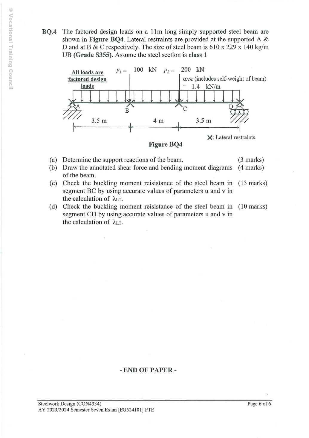
Read the diagram and collect the data
Lookup: Data File pp.9–10, exact UB row. Dimensions on p.9; properties on p.10. is overall depth; is the clear web depth between root fillets, not the nominal designation.
| Property | Lookup value / conversion |
|---|---|
| Dimensions | D617.2, web t 13.1, flange T22.1, root r 12.7, clear d 547.6, all |
| Local ratios | ; |
| Major-axis properties | ; ; |
| LTB properties | ; ; torsional index |
Before calculating: recognition and strategy
Use global equilibrium for the complete beam. Then determine the critical section from shear changes and evaluate the BMD over each specified lateral segment. The full UDL creates curvature even between the point loads; retain it when computing quarter-point moment factors.
(a) Support reactions —3 printed marks
Simple explanation: Why reactions balance the loads
Think of a seesaw that must neither fall nor turn.
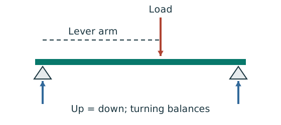
- Upward and downward forces must balance.
- Take moments about a support to eliminate its reaction.
- Use perpendicular distance from the point to the force line.
Remember: A lateral restraint is not automatically a vertical support.
Animation labBalance reactions and moments
Supplement to the original lesson. Enable JavaScript to play, step through calculations and rotate 3D models. The following explanation remains readable offline.
- This demonstrator is a simply supported 6 m beam with a 60 kN point load; it is not the page’s original loading diagram.
- . Moving the load towards B increases .
- . The two upward reactions must sum to P.
- With the load at midspan, . End couples, UDLs and overhangs require their own equilibrium terms.
(b) Annotated shear and bending diagrams —4 printed marks
| Position | Shear just before/after () | Moment () |
|---|---|---|
| / | ||
| / | ||
| / | ||
| / |
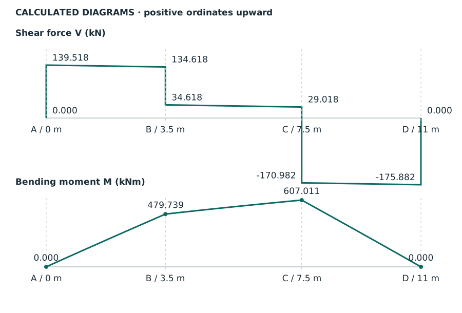
Animation labBuild the shear and moment diagrams
Supplement to the original lesson. Enable JavaScript to play, step through calculations and rotate 3D models. The following explanation remains readable offline.
- For the illustrative 60 kN point load on a 6 m simply supported beam, balance the reactions before making a cut.
- and before the point load. Moment grows linearly.
- Shear jumps down by P. To its right, and .
- For this case, moment is continuous and returns to zero at B. A concentrated applied couple instead creates a moment jump.
(c) BC segment LTB —13 printed marks
Simple explanation: A beam can escape sideways
The compressed flange can move sideways while the section twists.
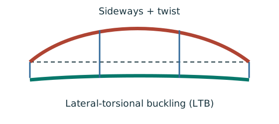
- Divide the beam at effective lateral restraints.
- Use each segment’s effective length to obtain its buckling resistance.
- Compare that resistance with the segment’s equivalent moment demand.
Remember: A section bending check alone does not check lateral-torsional buckling.
Flange thickness means that, despite the S355 grade name, use . In the model above, BC’s effective length is . The quarter-point calculation is shown explicitly below:
Local quarter positions are ,, measured fromA. Use the full beam evaluated there; segment distance and global are different quantities.
Normal-load effective length is the given segment length. All quantities in and λᴸᵀ are dimensionless. This Class 1 section has .
Table 8.3a, Data File p.5, pᵧ345 column:
Animation labA beam bends sideways and twists
Supplement to the original lesson. Enable JavaScript to play, step through calculations and rotate 3D models. The following explanation remains readable offline.
- For the illustrated sagging beam the top flange is compressed.
- The unrestrained compression flange can move sideways while the complete cross-section twists.
- Only effective restraints divide the member into unbraced segments. They do not automatically add vertical supports.
- Use the segment effective length, section properties and matching moment factor. This is an exaggerated mode shape, not a calculated displacement.
(d) CD segment LTB —10 printed marks
Simple explanation: Why the shape of the moment diagram matters
The same peak moment is more demanding when a long region stays near that peak.
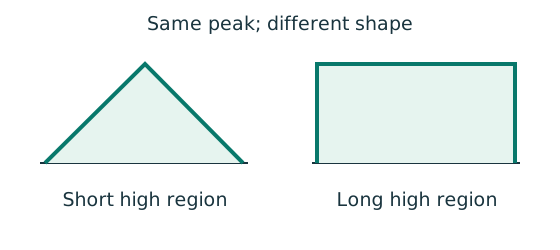
- Use the diagram of this unrestrained segment.
- Choose the applicable course sketch or quarter-point rule.
- Apply its factor to the demand, following the stated check.
Remember: Column flexural-buckling factors and LTB factors are not interchangeable.
CD is long. Its UDL means the BMD is slightly curved, so do not replace the full calculation by an exact triangularβ0 case. At all three quarter positions, subtract both and point-load moment contributions.
Local quarter positions are ,, measured fromA. Use the full beam evaluated there; segment distance and global are different quantities.
Normal-load effective length is the given segment length. All quantities in and λᴸᵀ are dimensionless. This Class 1 section has .
Table 8.3a, Data File p.5, pᵧ345 column:
Both requested segments pass under the stated restraint model. The paper does not ask forAB buckling in this question; do not label the whole beam fully checked merely becauseBC/CD pass.
Animation labA beam bends sideways and twists
Supplement to the original lesson. Enable JavaScript to play, step through calculations and rotate 3D models. The following explanation remains readable offline.
- For the illustrated sagging beam the top flange is compressed.
- The unrestrained compression flange can move sideways while the complete cross-section twists.
- Only effective restraints divide the member into unbraced segments. They do not automatically add vertical supports.
- Use the segment effective length, section properties and matching moment factor. This is an exaggerated mode shape, not a calculated displacement.
Compact exam answer
RA139.518182,RD175.881818 kN. MB479.738636,MC607.011364 kNm; maximum shear . py 345. BC:LE4 m,mLT0.919476,demand ,λLT64.701095,pb 235.016276,Mb 973.437414 kNm → passes. CD:LE3.5 m,mLT0.602560,demand ,λLT57.483259,pb 259.556920,Mb 1075.084763 kNm → passes. Retain UDL curvature and the stated normal-load/ assumption.
Mistakes to avoid
- Do not factor again.
- Do not make B/C vertical supports.
- Use forT22.1 mm.
- Use and segment lengths, not the full in both checks.
- Quarter positions must be local to the chosen segment.
Procedure for an unfamiliar variant
- Solve full-beam reactions including the UDL resultant.
- Write piecewise shear/moment equations.
- Use shear signs to locate the actual maximum.
- For each requested segment, evaluate its own quarter moments and factor.
- Read exact section properties and thickness-dependent strength, then calculate / and interpolatepb.
- Report each segment result and scope.
Independent self-check
Try it yourself. Invented variant: replace the design UDL by zero, keeping both point loads. Can you keep the sameBC/CD moment factors?
Reveal answer and reasoning
No. Reactions and allBMD ordinates change, and the segment diagrams become straight between point loads. Recompute both end moments and use the applicable straight-line moment factor. The section properties and the stated restraint lengths remain unchanged.