Connection example 8: flange welds carry moment, web welds carry shear
Open “Animation lab” beside a teaching step for a visual explanation or a walkthrough of its original expressions. Models are illustrative; source answers remain unchanged.
← Read this lecture example beside its chapter concepts
Need a simpler picture? Open “Simple explanation” beside a difficult step. These optional notes do not replace the full solution.
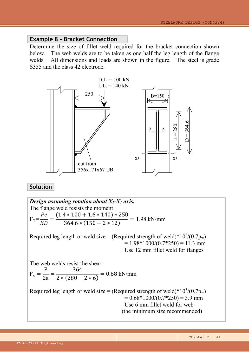
Design the bracket welds for dead plus imposed load at from the support. The bracket is cut from a UB. The specified web-weld leg is half the flange-weld leg. Use S355 and Class 42 electrode.
Original source: LectureNotes/Ch 2_Connection.pdf — p. 41. Values tagged given are in the question or diagram; lookup values come from a named table; calculated values follow from the working; assumptions are stated explicitly.
Read the diagram and collect the data
| Input | Origin |
|---|---|
| Given load | dead, imposed; downward arrow at from connection face. |
| Given weld geometry | across flange run; vertical arm; web run; all explicitly dimensioned. |
| Given size relationship | 。 |
| Lookup/model | . Rotate about at bottom flange; flange weld takes moment, two web welds take direct shear. This is the source’s simplified force allocation. |
Before calculating: recognition and strategy
Do not treat this as a rectangular in-plane torsion weld. The vertical load outside the supporting face produces flange tension and compression. Moment equilibrium gives tensile flange force . Divide that force by the effective flange weld length to get demand per millimetre. Because effective length depends on chosen leg, select a trial leg and verify it self-consistently.
1. Design force and force couple
Animation labSeparate the moment couple and shear
Supplement to the original lesson. Enable JavaScript to play, step through calculations and rotate 3D models. The following explanation remains readable offline.
- A simplified moment connection assigns different actions to different fastener groups.
- Opposite flange forces separated by z resist moment: .
- The web fasteners or welds carry the assigned vertical shear in this model.
- Flange force, web shear, plate bearing and detailing each need their specified checks.
2. Trial flange fillets
Simple explanation: How two flange forces make a moment
Two opposite forces form a turning pair, like two hands turning a wheel.
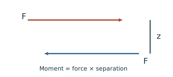
- Identify the separation between their actual force lines.
- Required force equals moment divided by that separation.
- Design the relevant flange group for that force.
Remember: The force-line separation is not automatically the overall section depth.
The source tries . The available run loses at its ends, leaving effective. Use the printed weld run , not the nominal section width.
This also solves the implicit inequality by a verified trial. Increasing improves throat but shortens effective length, so do not omit the recheck.
Animation labFrom fillet leg to effective throat
Supplement to the original lesson. Enable JavaScript to play, step through calculations and rotate 3D models. The following explanation remains readable offline.
- An equal-leg fillet between perpendicular plates has an approximately right-triangular section.
- For this geometry, throat . It is shorter than the leg.
- Effective resisting area = . With here, capacity per length is .
- Use the course end allowances, minimum size and length rules; increasing the geometric length alone does not resolve every detailing check.
3. Apply the required half-size rule and check shear
Simple explanation: Why the weld throat is smaller than its leg
The shortest cut through the weld is thinner than the outside leg.
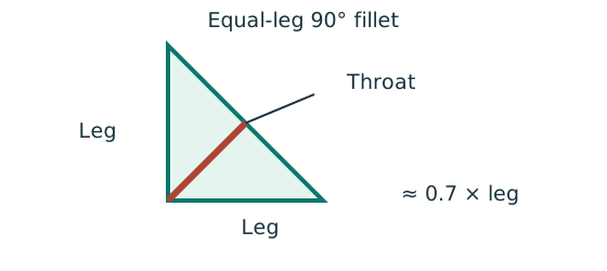
- For the stated equal-leg 90° fillet, throat is approximately 0.7 × leg.
- Multiply throat area by the matching weld design strength.
- For force per length, use a one-millimetre weld strip.
Remember: Choose strength from both the steel grade and electrode class.
Even though strength alone needs only about , use to satisfy the given relationship to the flange weld.
Animation labFrom fillet leg to effective throat
Supplement to the original lesson. Enable JavaScript to play, step through calculations and rotate 3D models. The following explanation remains readable offline.
- An equal-leg fillet between perpendicular plates has an approximately right-triangular section.
- For this geometry, throat . It is shorter than the leg.
- Effective resisting area = . With here, capacity per length is .
- Use the course end allowances, minimum size and length rules; increasing the geometric length alone does not resolve every detailing check.
4. Check lengths and identify the remaining thickness condition
Simple explanation: Drawn length and useful length differ
The start and end of a weld are not credited as fully effective in this course model.
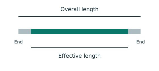
- Find the effective length required by strength.
- Add the specified end allowance to each separate run.
- Round up, then check minimum size, spacing and returns.
Remember: Strength alone does not prove a weld detail is acceptable.
The source dimensions describe weld runs on the cut bracket, not a licence to infer other fabrication details from scale. The supporting column thickness is not stated. The result therefore establishes flange/web weld strength and the size ratio; applicability of the thicker-part minimum-size rule to the support must be confirmed separately.
Animation labFrom fillet leg to effective throat
Supplement to the original lesson. Enable JavaScript to play, step through calculations and rotate 3D models. The following explanation remains readable offline.
- An equal-leg fillet between perpendicular plates has an approximately right-triangular section.
- For this geometry, throat . It is shorter than the leg.
- Effective resisting area = . With here, capacity per length is .
- Use the course end allowances, minimum size and length rules; increasing the geometric length alone does not resolve every detailing check.
Compact exam answer
,. About , flange force. flange weld has effective length and resistance. web welds each have effective length, combined resistance . Both pass and web leg is half flange leg. Support thickness for minimum weld-size verification is not supplied.
Mistakes to avoid
- The moment arm is ; the web run is . They are not interchangeable.
- Use two web welds, but the source’s tension-flange force is resisted by the specified flange run.
- Subtract using that run’s own leg size.
Procedure for an unfamiliar variant
- Identify the source pivot and the flange-force arm.
- Factor load and calculate moment/force couple.
- Try a flange leg, calculate its effective length and verify capacity.
- Apply the specified web/flange size relationship and check web shear.
- Check effective-length/detailing rules and state unprovided support data.
Independent self-check
Try it yourself. Keep the selected welds and increase the eccentricity to . What happens to the flange strength check?
Reveal answer and reasoning
Flange force becomes , greater than . The flange weld fails while the unchanged direct web shear remains and still passes.
Animation labSeparate the moment couple and shear
Supplement to the original lesson. Enable JavaScript to play, step through calculations and rotate 3D models. The following explanation remains readable offline.
- A simplified moment connection assigns different actions to different fastener groups.
- Opposite flange forces separated by z resist moment: .
- The web fasteners or welds carry the assigned vertical shear in this model.
- Flange force, web shear, plate bearing and detailing each need their specified checks.