Connection example 6: balance two weld lengths about the load line
Open “Animation lab” beside a teaching step for a visual explanation or a walkthrough of its original expressions. Models are illustrative; source answers remain unchanged.
← Read this lecture example beside its chapter concepts
Need a simpler picture? Open “Simple explanation” beside a difficult step. These optional notes do not replace the full solution.
Design the side fillet welds for a angle carrying characteristic dead tension and characteristic imposed tension through its centroid. Use S355 steel and Class 42 electrode.
Original source: LectureNotes/Ch 2_Connection.pdf — p. 38. Values tagged given are in the question or diagram; lookup values come from a named table; calculated values follow from the working; assumptions are stated explicitly.
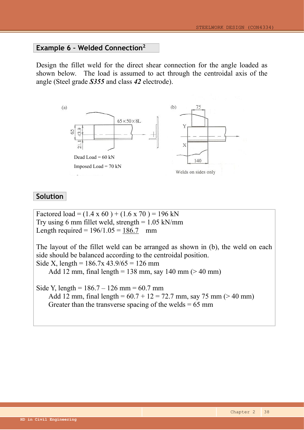
Read the diagram and collect the data
| Input | Origin |
|---|---|
| Given loads | dead, imposed, arrows through dashed centroidal axis. |
| Given geometry | The left sketch labels L; connected-leg width , centroid distance and . |
| Design choice | Lecturer tries fillet and final side lengths (X), (Y), shown at right. |
| Lookup | Table 9.2a, S355 row/Class 42 column: . Throat . |
Before calculating: recognition and strategy
A longer weld must be put on the side closer to the load line. Treat the two parallel weld lines as supports of the tensile force across the separation: force equilibrium gives ; moment equilibrium about X gives . Equal weld lengths would move the connection resultant away from the angle centroid.
1. Factored tensile force
Animation labFrom characteristic to design load
Supplement to the original lesson. Enable JavaScript to play, step through calculations and rotate 3D models. The following explanation remains readable offline.
- G is permanent load; Q is imposed load. A surface load and a line load also have different units.
- This illustration uses the course gravity case . Other combinations in the original text retain their own factors.
- For illustrative , change Q and watch each separate contribution.
- Do not carry this ULS total automatically into deflection. Follow the stated SLS load case.
2. Select a trial leg and find capacity per length
Simple explanation: Why the weld throat is smaller than its leg
The shortest cut through the weld is thinner than the outside leg.
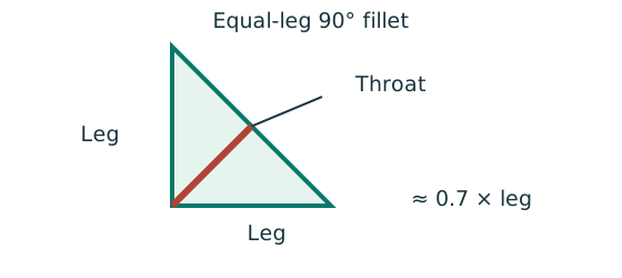
- For the stated equal-leg 90° fillet, throat is approximately 0.7 × leg.
- Multiply throat area by the matching weld design strength.
- For force per length, use a one-millimetre weld strip.
Remember: Choose strength from both the steel grade and electrode class.
The angle edge thickness is , so the source maximum edge-weld leg permits this selection. The supporting plate thickness is not given; its effect on the minimum weld-size rule remains a detailing condition.
Animation labFrom fillet leg to effective throat
Supplement to the original lesson. Enable JavaScript to play, step through calculations and rotate 3D models. The following explanation remains readable offline.
- An equal-leg fillet between perpendicular plates has an approximately right-triangular section.
- For this geometry, throat . It is shorter than the leg.
- Effective resisting area = . With here, capacity per length is .
- Use the course end allowances, minimum size and length rules; increasing the geometric length alone does not resolve every detailing check.
3. Share force and effective length between the sides
Simple explanation: Why two weld lengths can be unequal
Two side welds must balance the load about its actual line of action.
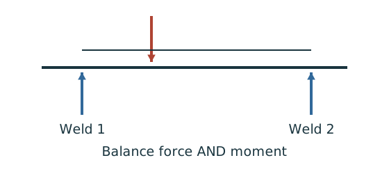
- Find the load line and the lever arm to each weld.
- Balance moments as well as the total force.
- Convert each weld’s force into its own required length.
Remember: Equal-looking legs do not justify equal weld forces without equilibrium.
Check: the forces sum and the required lengths sum . The larger opposite lever arm produces the larger SideX force.
Animation labBalance two weld forces
Supplement to the original lesson. Enable JavaScript to play, step through calculations and rotate 3D models. The following explanation remains readable offline.
- The angle centroid/load line is generally not halfway between the two weld runs.
- . Both weld runs contribute to the applied force.
- . The run nearer the load line carries more force.
- For equal throat resistance per length, the required effective lengths follow the same ratio. Add detailing allowances afterwards.
4. Add end allowances, round up and check the actual lengths
Simple explanation: Drawn length and useful length differ
The start and end of a weld are not credited as fully effective in this course model.
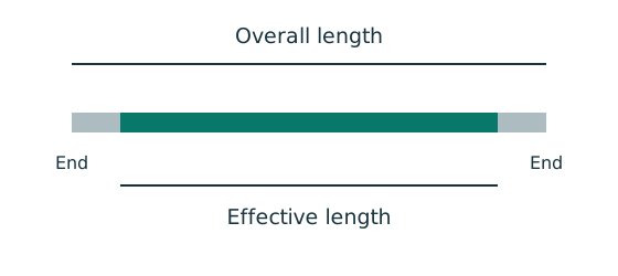
- Find the effective length required by strength.
- Add the specified end allowance to each separate run.
- Round up, then check minimum size, spacing and returns.
Remember: Strength alone does not prove a weld detail is acceptable.
Each effective length exceeds . The physical side lengths and also exceed the transverse separation, matching the source detailing check. The extra rounding increases available resistance; the actual force split still follows equilibrium. End-return/support-plate details are not fully specified, so this is the completed requested side-weld strength/length design, not a complete fabrication detail.
Animation labFrom fillet leg to effective throat
Supplement to the original lesson. Enable JavaScript to play, step through calculations and rotate 3D models. The following explanation remains readable offline.
- An equal-leg fillet between perpendicular plates has an approximately right-triangular section.
- For this geometry, throat . It is shorter than the leg.
- Effective resisting area = . With here, capacity per length is .
- Use the course end allowances, minimum size and length rules; increasing the geometric length alone does not resolve every detailing check.
Compact exam answer
. Use fillet, . Force split X/Y=/. Required effective lengths /. Add to each and provide (X), (Y); effective capacities / exceed the assigned forces.
Mistakes to avoid
- Read the angle label: the source says thick, not .
- Use the opposite centroid lever arm when allocating weld force.
- Add separately to both weld runs.
- Do not use total capacity alone if one side is too short.
Procedure for an unfamiliar variant
- Locate the centroidal load line and both weld lines.
- Factor loads and select a permitted trial weld leg.
- Use force and moment equilibrium for the two side forces.
- Divide each force by weld strength per length.
- Add individual end deductions back, round up, and recheck each side.
Independent self-check
Try it yourself. Suppose the same force acts midway between the -spaced weld lines. What physical length is required on each side for weld?
Reveal answer and reasoning
Each side takes . Required effective length. Add ; choose each. Centred loading makes equal lengths appropriate.
Animation labBalance two weld forces
Supplement to the original lesson. Enable JavaScript to play, step through calculations and rotate 3D models. The following explanation remains readable offline.
- The angle centroid/load line is generally not halfway between the two weld runs.
- . Both weld runs contribute to the applied force.
- . The run nearer the load line carries more force.
- For equal throat resistance per length, the required effective lengths follow the same ratio. Add detailing allowances afterwards.