Connection example 5: separate moment and shear bolt groups
Open “Animation lab” beside a teaching step for a visual explanation or a walkthrough of its original expressions. Models are illustrative; source answers remain unchanged.
← Read this lecture example beside its chapter concepts
Need a simpler picture? Open “Simple explanation” beside a difficult step. These optional notes do not replace the full solution.
Design the bolt groups joining a UB floor beam to a UC. Steel is S355 and bolts are Grade 8.8 M24. Characteristic moments are dead and imposed; characteristic shears are dead and imposed.
Original source: LectureNotes/Ch 2_Connection.pdf — p. 29, p. 30. Values tagged given are in the question or diagram; lookup values come from a named table; calculated values follow from the working; assumptions are stated explicitly.
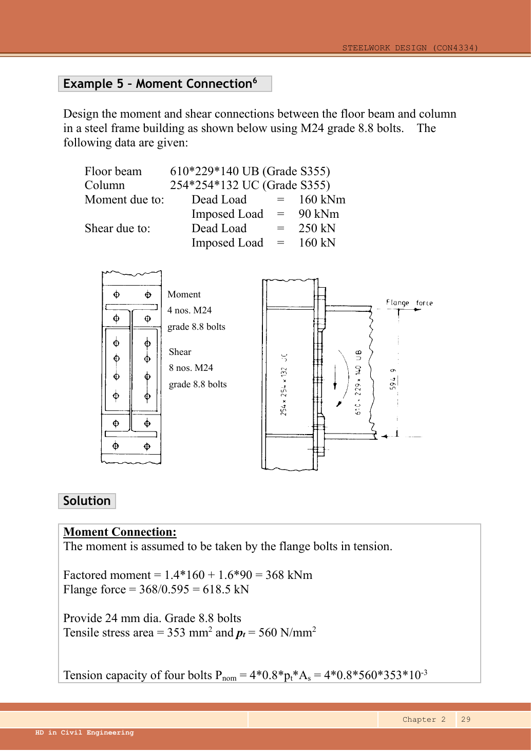
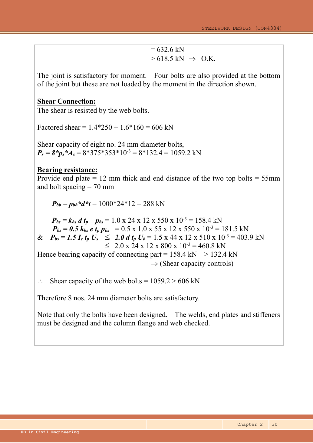
Read the diagram and collect the data
| Input | Origin |
|---|---|
| Given actions | Separate moment and shear dead/imposed components in question table; factor each once. |
| Given force-couple arm | between flange force lines in lecturer diagram/solution; not the nominal beam depth. |
| Selected fasteners | Four upper flange bolts; four lower for opposite moment direction; eight web bolts, all M24. |
| Selected bearing detail | Lecturer p.30 selects end plate, end distance and pitch. These are design choices, not task givens. |
| Lookup | M24 ; Grade 8.8 ,,; S355 ,; . |
Before calculating: recognition and strategy
Use the source idealisation: bending is a tension/compression force couple at the flanges; vertical shear is carried by a separate web-bolt group. Moment divided by the perpendicular couple arm gives flange force. Because groups have separate assigned actions, do not distribute the flange tensile force among the web bolts.
1. Design the tension flange group
Simple explanation: How two flange forces make a moment
Two opposite forces form a turning pair, like two hands turning a wheel.
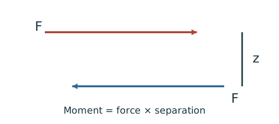
- Identify the separation between their actual force lines.
- Required force equals moment divided by that separation.
- Design the relevant flange group for that force.
Remember: The force-line separation is not automatically the overall section depth.
For the moment direction shown, the lower flange region supplies compression and the upper group tension. The extra lower four bolts are not added to the upper group’s capacity; they provide the corresponding group for the opposite moment direction/detail.
Animation labOut-of-plane bolt tension and prying
Supplement to the original lesson. Enable JavaScript to play, step through calculations and rotate 3D models. The following explanation remains readable offline.
- A bracket moment can create compression at the plate contact and tension in the bolt rows.
- The original assumed pivot/compression line determines each row distance.
- Under the elastic row model, a farther tension row attracts more tension. Direct shear may act simultaneously.
- Flexible plates can add prying force. Use nominal tension and interaction rules exactly as specified by the course.
2. Design the shear group
Simple explanation: Count where the bolt can be sheared
The plate interfaces are the places trying to cut across the bolt.
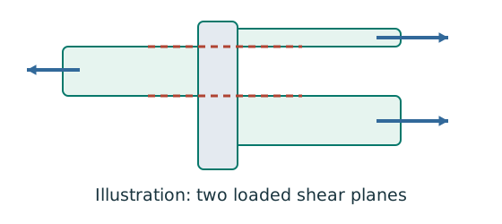
- Count actual loaded shear planes, not merely visible plates.
- Choose shank or threaded area for the plane concerned.
- Compare group resistance with the force that group transfers.
Remember: Bolts on opposite sides of a splice do not all act in parallel.
Animation labCount the bolt shear planes
Supplement to the original lesson. Enable JavaScript to play, step through calculations and rotate 3D models. The following explanation remains readable offline.
- Load must cross an interface between the connected plates.
- A lap joint gives one shear plane through a bolt.
- A symmetric double-cover joint may provide two shear planes. Count load-transfer interfaces, not just visible plates.
- Use the source’s area and shear strength. Then check bearing, plate resistance and detailing separately.
3. Check selected end-plate bearing
Use and standard hole . The chosen plate and pitch give clear ligament . The chosen end distance is .
Both bearing resistances exceed the per-bolt demand and also exceed the shear resistance, so shear governs the web group.
Animation labBearing and the remaining ligament
Supplement to the original lesson. Enable JavaScript to play, step through calculations and rotate 3D models. The following explanation remains readable offline.
- Force transfers through contact between bolt and connected plate.
- The plate around the hole carries bearing stress. Bolt bearing and plate bearing are separate checks.
- A short ligament can tear out towards the end. The direction of force determines the relevant edge.
- Evaluate every specified bearing and ligament bound for each layer and retain the smallest applicable resistance.
4. State what has actually been designed
Simple explanation: What to do when one input is missing
A calculator cannot supply a dimension that the drawing never gave.
- Separate given values, table values and calculated values.
- Complete the checks whose required inputs are available.
- State the missing input beside the remaining conditional result.
Remember: An illustrative assumption must not become an unstated exam given.
The flange tension and web shear/bearing bolt checks pass under the source’s force-couple idealisation. The source explicitly says only bolts have been designed; welds, end plates, stiffeners, column flange and column web require separate design. The end-plate bearing calculation is not a complete end-plate bending/prying check.
Animation labSeparate the moment couple and shear
Supplement to the original lesson. Enable JavaScript to play, step through calculations and rotate 3D models. The following explanation remains readable offline.
- A simplified moment connection assigns different actions to different fastener groups.
- Opposite flange forces separated by z resist moment: .
- The web fasteners or welds carry the assigned vertical shear in this model.
- Flange force, web shear, plate bearing and detailing each need their specified checks.
Compact exam answer
ULS ; flange force. Four M24 Grade 8.8 flange bolts give nominal tension . ULS ; eight M24 web bolts give shear . Selected plate gives bolt bearing and plate bearing per bolt, both. Bolts pass; remaining connection components are outside the source calculation.
Mistakes to avoid
- Use force-couple arm, not nominal beam depth .
- Do not add bottom compression-side bolts to the upper tensile group.
- Do not call the end plate fully designed after checking only bearing.
Procedure for an unfamiliar variant
- Factor moment and shear components separately.
- Resolve bending moment into flange force using the stated couple arm.
- Size the tension group using nominal bolt tension.
- Assign shear to the web group and check its bearing path.
- Document which other joint components are not included in the bolt-only exercise.
Independent self-check
Try it yourself. If the ultimate moment becomes , keeping arm and four flange bolts, is the tension group adequate?
Reveal answer and reasoning
, so no. Required count; at least by strength alone, but the final symmetric layout and plate/prying design must also be revised.
Animation labOut-of-plane bolt tension and prying
Supplement to the original lesson. Enable JavaScript to play, step through calculations and rotate 3D models. The following explanation remains readable offline.
- A bracket moment can create compression at the plate contact and tension in the bolt rows.
- The original assumed pivot/compression line determines each row distance.
- Under the elastic row model, a farther tension row attracts more tension. Direct shear may act simultaneously.
- Flexible plates can add prying force. Use nominal tension and interaction rules exactly as specified by the course.