Solve the complete compulsory question, using the original diagram beside the calculation.
Independent teaching answer, not an official solution or marking scheme. Printed marks are retained. Read the source conditions beside each result.
Read the load path first
The slab arrows point across adjacent B1 beams. Each interior B1 collects half the 2.5 m bay on either side: tributary width 2.5 m. Its labelled span is 7 m. The supporting B2 spans 5 m between the drawn columns and receives 1 B1 end reaction(s), at its middle.
Beams aligned directly with a column deliver their end reaction to that column, not as an extra midspan load on B2. The B2 point load is already factored; do not factor it again. The slab gives full compression-flange restraint, so this is section resistance rather than an LTB design.
Units: 1 kN = 1,000 N; 1 m = 1,000 mm; 1 cm³ = 1,000 mm³; 1 cm⁴ = 10,000 mm⁴. A demand is the load effect; a resistance is what the member can carry. Compare matching units.
Simple explanation — open only if needed
Think of a tray resting on small bars, then on two larger edge bars. Follow where each bar ends: that determines which reaction goes onto the next bar.
Load intensity [4 marks]
Given slab thickness 200 mm, finishes 2 kN/m², imposed load 2 kN/m². Convert thickness to metres. Permanent area load includes concrete and finishes; beam weight is added later as a line load.
gk=hγc+gfin=0.2(24.5)+2=6.9kN/m2
qu=1.4gk+1.6qk=1.4(6.9)+1.6(2)=12.86kN/m2
qu=1.4(0.2γc+2)+1.6(2)=0.28γc+6(kN/m2)
Compact exam answer — key result lines
gk=hγc+gfin=0.2(24.5)+2=6.9kN/m2
qu=1.4gk+1.6qk=1.4(6.9)+1.6(2)=12.86kN/m2
qu=1.4(0.2γc+2)+1.6(2)=0.28γc+6(kN/m2)
Given slab thickness 200 mm, finishes 2 kN/m², imposed load 2 kN/m². Convert thickness to metres. Permanent area load includes concrete and finishes; beam weight is added later as a line load.
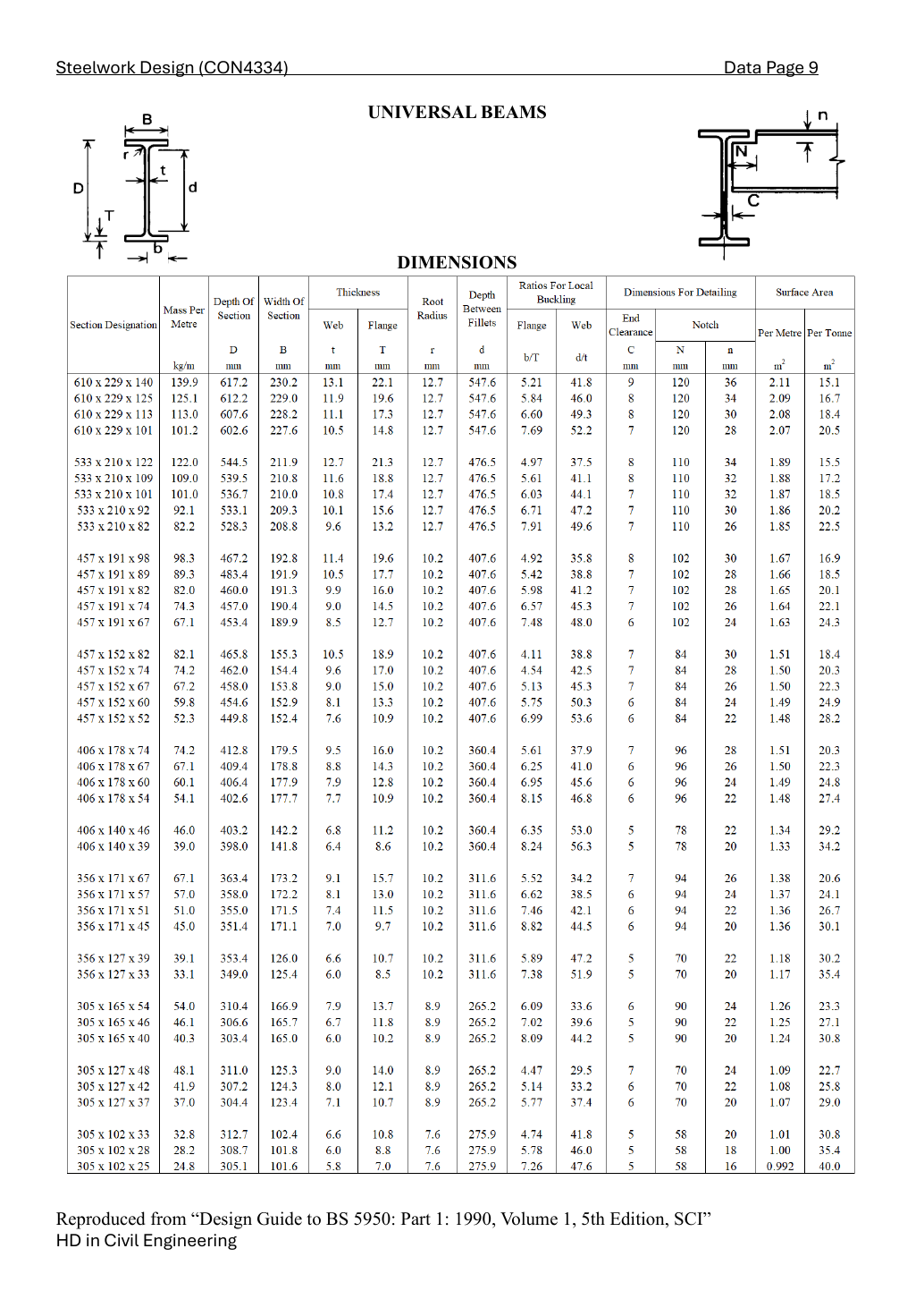
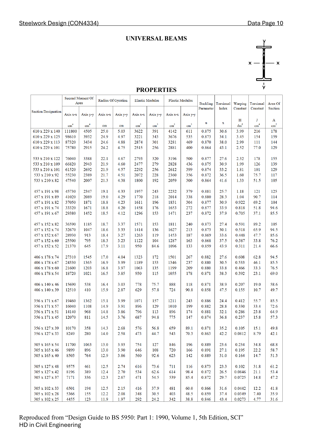
Lookup the exact 356 × 171 × 51 UB row. Read dimensions first, properties second. D = overall depth; t = web thickness; T = flange thickness; d = clear web depth. The designation is not an exact dimension.
Lookup the exact 305 × 165 × 54 UB row. Read dimensions first, properties second. D = overall depth; t = web thickness; T = flange thickness; d = clear web depth. The designation is not an exact dimension.
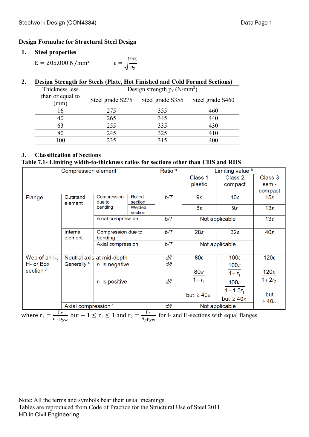
S355 design strength depends on the actual flange thickness. Local classification decides whether plastic bending resistance is allowed. In pure bending the web limit is different from uniform compression.
py=355N/mm2,ϵ=275/355=0.880141
b/T=7.46,9ϵ=7.921,10ϵ=8.801,13ϵ=11.442
d/t=42.1<80ϵ=70.411⟹Class1
Take the worse flange/web class. Class 1 or 2 permits the capped plastic modulus; Class 3 uses the elastic modulus.
S355 design strength depends on the actual flange thickness. Local classification decides whether plastic bending resistance is allowed. In pure bending the web limit is different from uniform compression.
py=355N/mm2,ϵ=275/355=0.880141
b/T=6.09,9ϵ=7.921,10ϵ=8.801,13ϵ=11.442
d/t=33.6<80ϵ=70.411⟹Class1
Take the worse flange/web class. Class 1 or 2 permits the capped plastic modulus; Class 3 uses the elastic modulus.
Compact exam answer — key result lines
b/T=7.46,9ϵ=7.921,10ϵ=8.801,13ϵ=11.442
d/t=42.1<80ϵ=70.411⟹Class1
py=355N/mm2,ϵ=275/355=0.880141
b/T=6.09,9ϵ=7.921,10ϵ=8.801,13ϵ=11.442
d/t=33.6<80ϵ=70.411⟹Class1
Take the worse flange/web class. Class 1 or 2 permits the capped plastic modulus; Class 3 uses the elastic modulus.
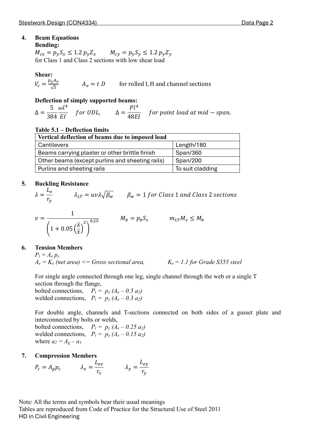
The web carries shear. For a rolled UB use Av = Dt, then the course shear resistance pyAv/√3. The 0.6 factor below is the low-shear threshold; it is not the coefficient in the shear-resistance formula.
Even the maximum shear is below 0.6Vc, so the low-shear moment resistance applies throughout.
For serviceability use unfactored imposed load only, E = 205,000 N/mm², I in mm⁴ and span in mm. Do not include the ULS factors or dead load in this course deflection limit.
The web carries shear. For a rolled UB use Av = Dt, then the course shear resistance pyAv/√3. The 0.6 factor below is the low-shear threshold; it is not the coefficient in the shear-resistance formula.
Even the maximum shear is below 0.6Vc, so the low-shear moment resistance applies throughout.
For serviceability use unfactored imposed load only, E = 205,000 N/mm², I in mm⁴ and span in mm. Do not include the ULS factors or dead load in this course deflection limit.
Both the conservative brittle-finish limit and the other-beam limit are met.
Beam-to-column welds [7 marks]
Leff=2(120−2(6))+2(250−2(6))=692mm
Rw=0.7(6)(692)(250)/1000=726.6kN
The original end view shows one weld on each outer flange face and a weld on each side of the web. With the given zero-eccentricity model, sum all four effective runs. At C1 the edge B1 has half the interior slab strip; do not use the interior B1 reaction for that end connection.
Each beam end has its own weld group; both direct-shear demands pass in the stated numerical branch.
Reusable exam procedure and mistakes
Trace the slab arrows and count reactions before doing arithmetic.
Use each member’s exact table row. Class 2 is not Class 1, but both allow capped plastic bending.
Never factor an already factored reaction twice; never include beam dead weight in imposed-load deflection.
Independent practice — invented variant
Invented variant: imposed load rises by 20%, with dead load unchanged. What changes?
Hint
Separate permanent and imposed terms before changing a load.
Reveal answer
Multiply imposed-only deflections by 1.2. Rebuild ULS load as 1.4G + 1.6(1.2Q); do not multiply the total ULS action by 1.2. Section capacities and classes stay unchanged.