All connection subparts from this paper, including the specified checks and source qualifications.
Independent teaching answer, not an official solution or marking scheme. Printed marks are retained. Read the source conditions beside each result.
Recognise the connection model
Units: 1 kN = 1,000 N; 1 m = 1,000 mm; 1 cm³ = 1,000 mm³; 1 cm⁴ = 10,000 mm⁴. A demand is the load effect; a resistance is what the member can carry. Compare matching units.
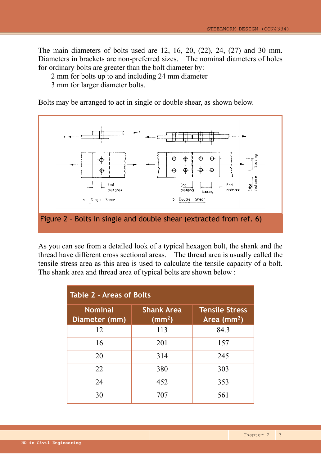
A splice transfers axial force through stages. A side-plate bracket creates in-plane torsion. An end-plate bracket creates bolt tension. Identify which picture applies before selecting a formula.
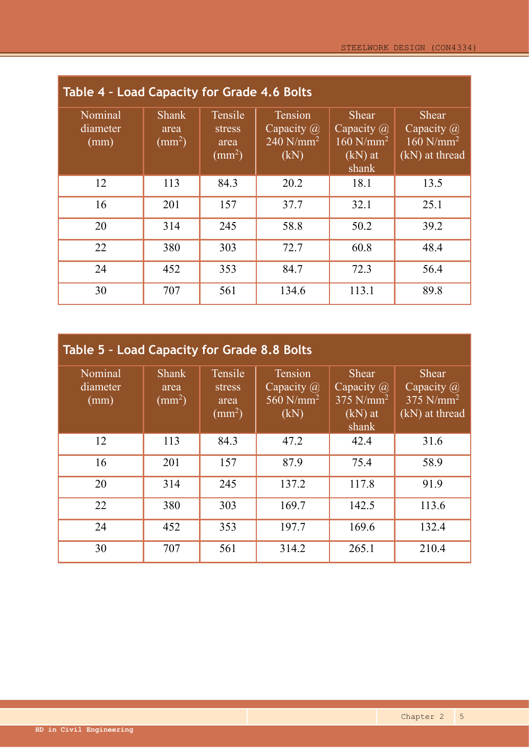
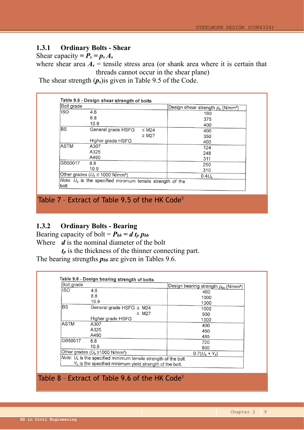
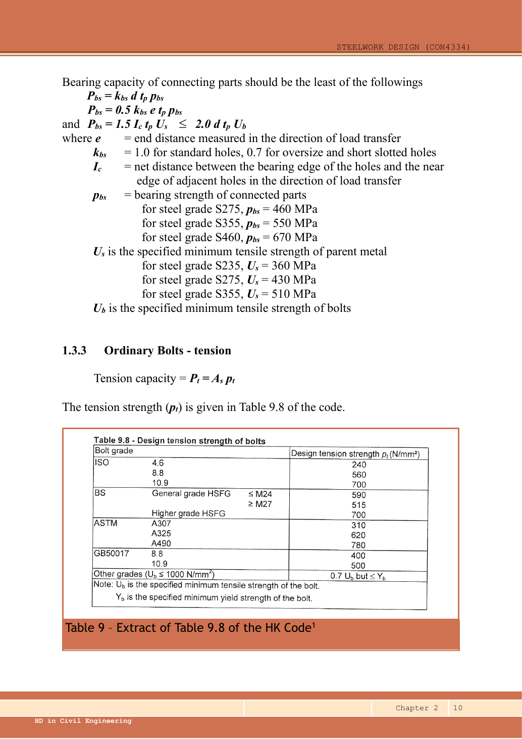
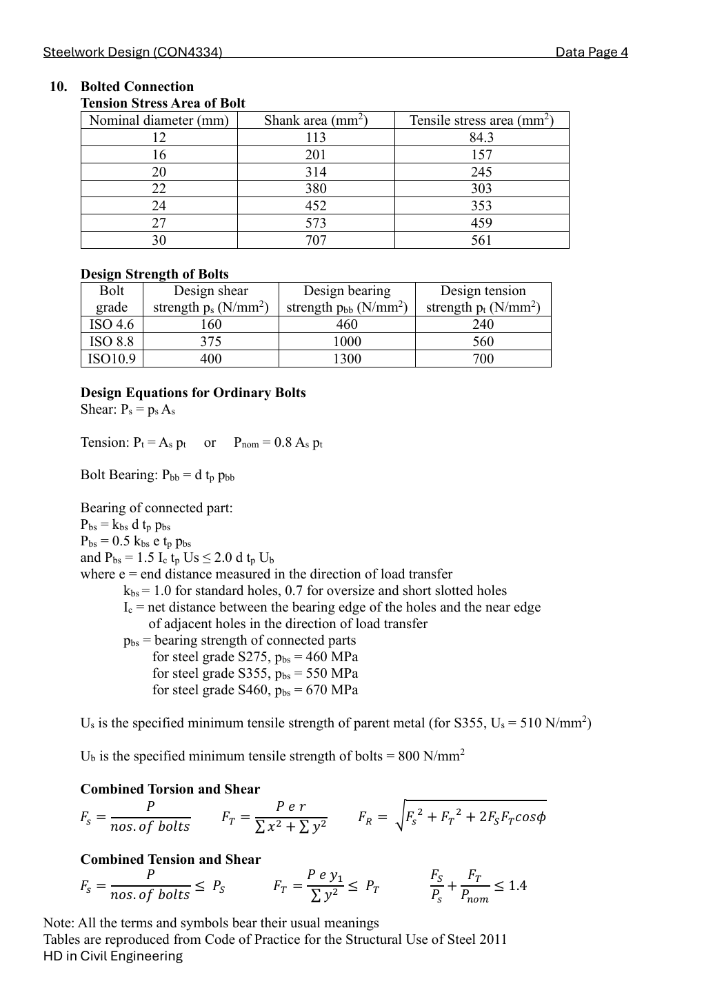
Grade 8.8: shear strength ps = 375, bolt bearing pbb = 1000, ultimate bolt strength Ub = 800 N/mm². S355 plate: pbs = 550, Us = 510 N/mm², Ke = 1.1. Use threaded stress area As for the conservative shear plane, nominal d for bearing, and hole diameter d0 for material removed.
The two symmetric side plates share the total force and moment equally. Work on ONE plate, using bolt coordinates measured from that plate’s bolt-group centroid. A bolt connecting this side plate to its column flange is in single shear.
Direct shear P/n acts equally on each bolt. Torsion adds a force perpendicular to the radius. At the most loaded corner, its vertical component adds to direct shear; calculate both components before the resultant.
Direct shear P/n acts equally on each bolt. Torsion adds a force perpendicular to the radius. At the most loaded corner, its vertical component adds to direct shear; calculate both components before the resultant.
Check bolts and parts [18 marks]
Ps=245(375)/1000=91.875kN>0
FAIL
Pbb,plate=20(20)(1000)/1000=400kN
The column flange is another connected part. Its actual thickness must also pass; compare the lower bolt-bearing resistance.
Tcolumn≥FR/(dpbb)=133.93236/20=6.696618mm
Rbs,basic=20(20)(550)/1000=220kN
For the vector force, check distance to the edge and neighbouring hole in the bearing direction. A conservative independent-component check uses each component divided by its directional resistance and requires their sum ≤ 1. It bounds a linear interaction rather than pretending the resultant acts vertically.
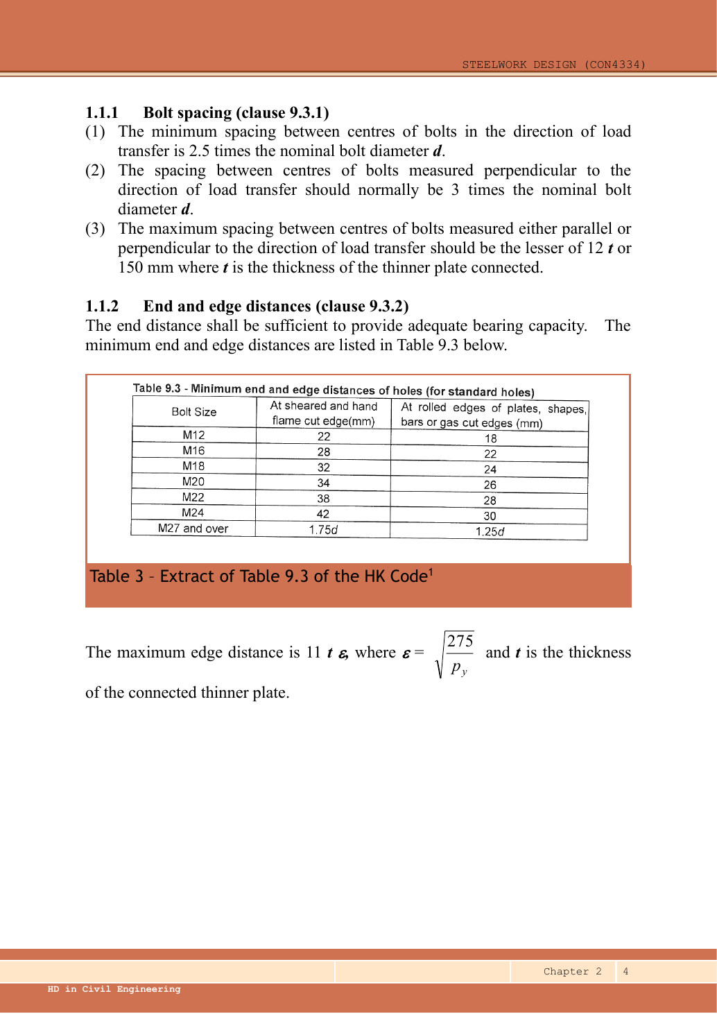
The transverse edge distance is absent, so the horizontal end-bearing limit remains unknown.
Compact exam answer — key result lines
Ps=245(375)/1000=91.875kN>0
Pbb,plate=20(20)(1000)/1000=400kN
Tcolumn≥FR/(dpbb)=133.93236/20=6.696618mm
Rbs,basic=20(20)(550)/1000=220kN
The transverse edge distance is absent, so the horizontal end-bearing limit remains unknown.
Reusable procedure and common errors
Draw the load-transfer stages. Count bolts and shear planes for one stage, then compare all failure modes.
Resolve eccentric forces as vectors. Never add perpendicular components arithmetically.
Use effective weld length and check size limits after strength; “strong enough” does not fix an impossible detail.
Independent practice — invented variant
Invented variant: all applied loads are 10% larger but geometry is unchanged. What scales, and what does not?
Hint
Isolate one load-transfer stage, then distinguish demand from fixed resistance.
Reveal answer
For these linear elastic models, bolt forces and weld force per unit length rise 10%; required strength-only weld throat also rises 10%. Bolt areas, section capacities, effective lengths of already specified welds and detailing limits stay unchanged. Recheck every utilisation.