All connection subparts from this paper, including the specified checks and source qualifications.
Independent teaching answer, not an official solution or marking scheme. Printed marks are retained. Read the source conditions beside each result.
Recognise the connection model
Units: 1 kN = 1,000 N; 1 m = 1,000 mm; 1 cm³ = 1,000 mm³; 1 cm⁴ = 10,000 mm⁴. A demand is the load effect; a resistance is what the member can carry. Compare matching units.
A splice transfers axial force through stages. A side-plate bracket creates in-plane torsion. An end-plate bracket creates bolt tension. Identify which picture applies before selecting a formula.
Check supplied weld length [8 marks]
The main plate width is 200 mm; each cover is 140 mm wide, with thicknesses 24 mm and 12 mm respectively. These come from the original width and side-view dimension chains. There are no bolt holes. The two covers act in parallel and each carries half the design tension.
Choose longitudinal welds on both edges of each cover, on each side of the main-plate butt: four parallel weld runs transfer the full force on one half. The other half repeats the load transfer. Count four, not eight, in the capacity of one stage.
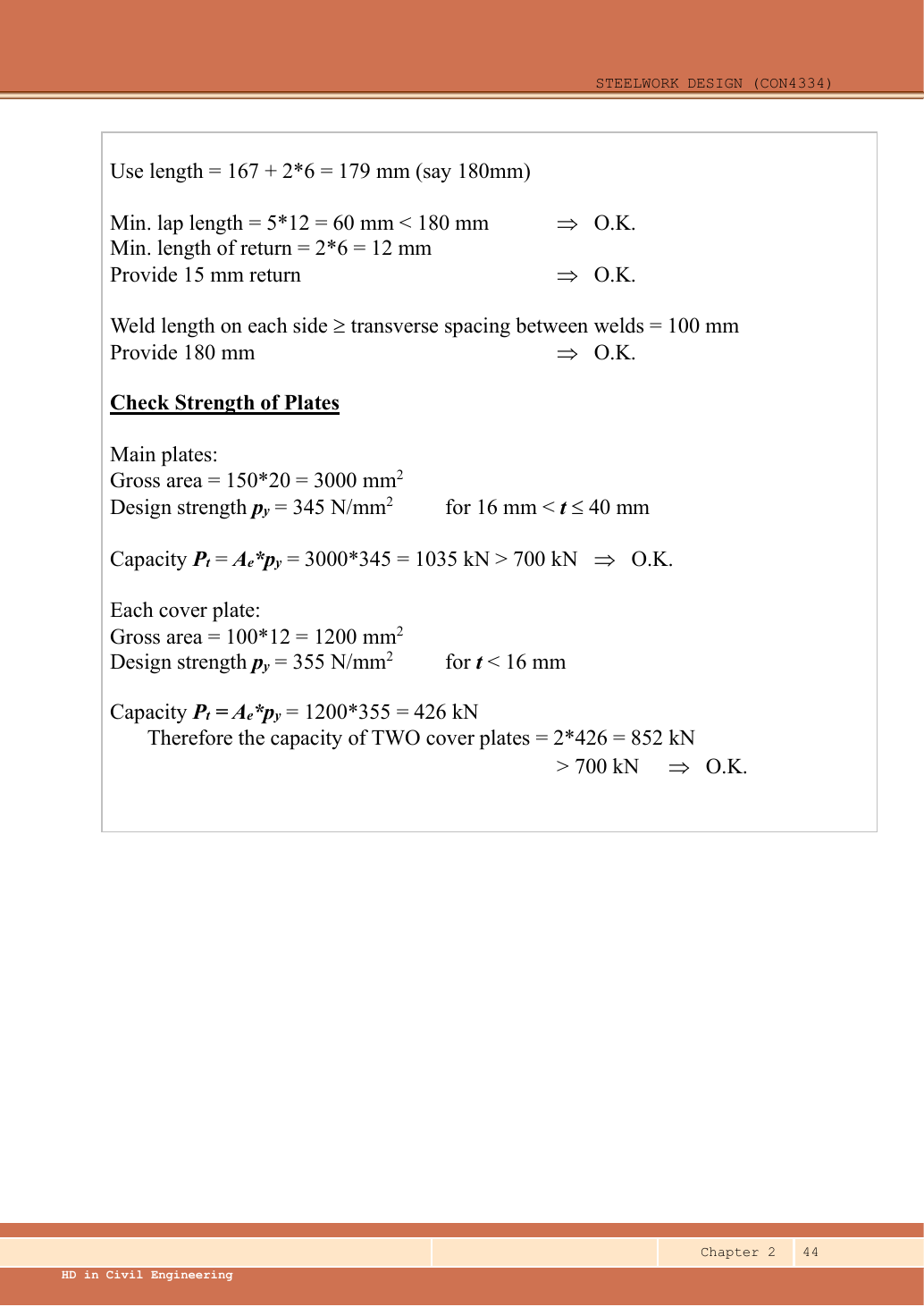
The dimension is 250 mm from each cover end to the centre of the 10 mm butt gap. Exclude half the gap from each force-transfer lap and the 2s end deduction; exclude the short 15 mm returns from resistance.
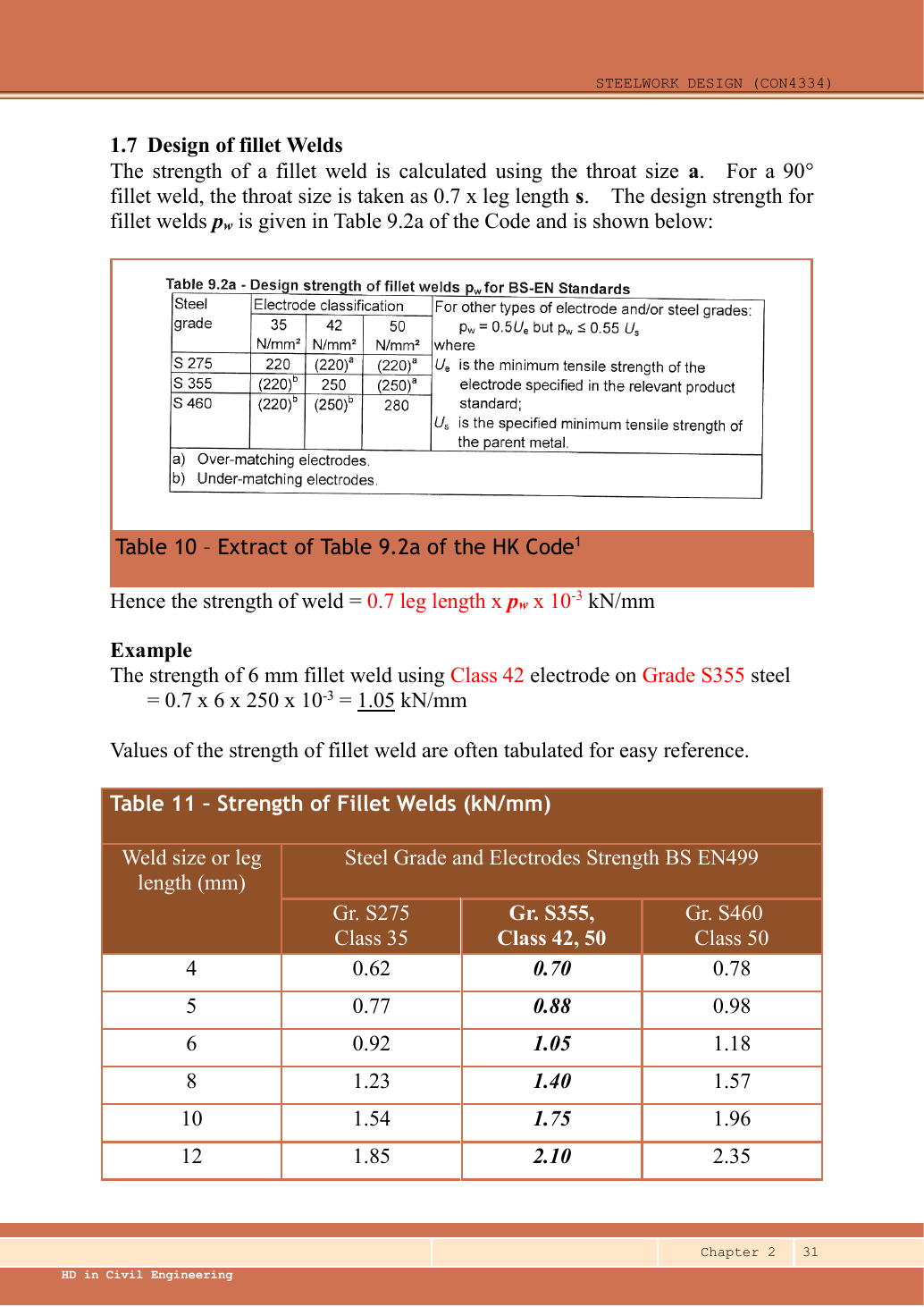
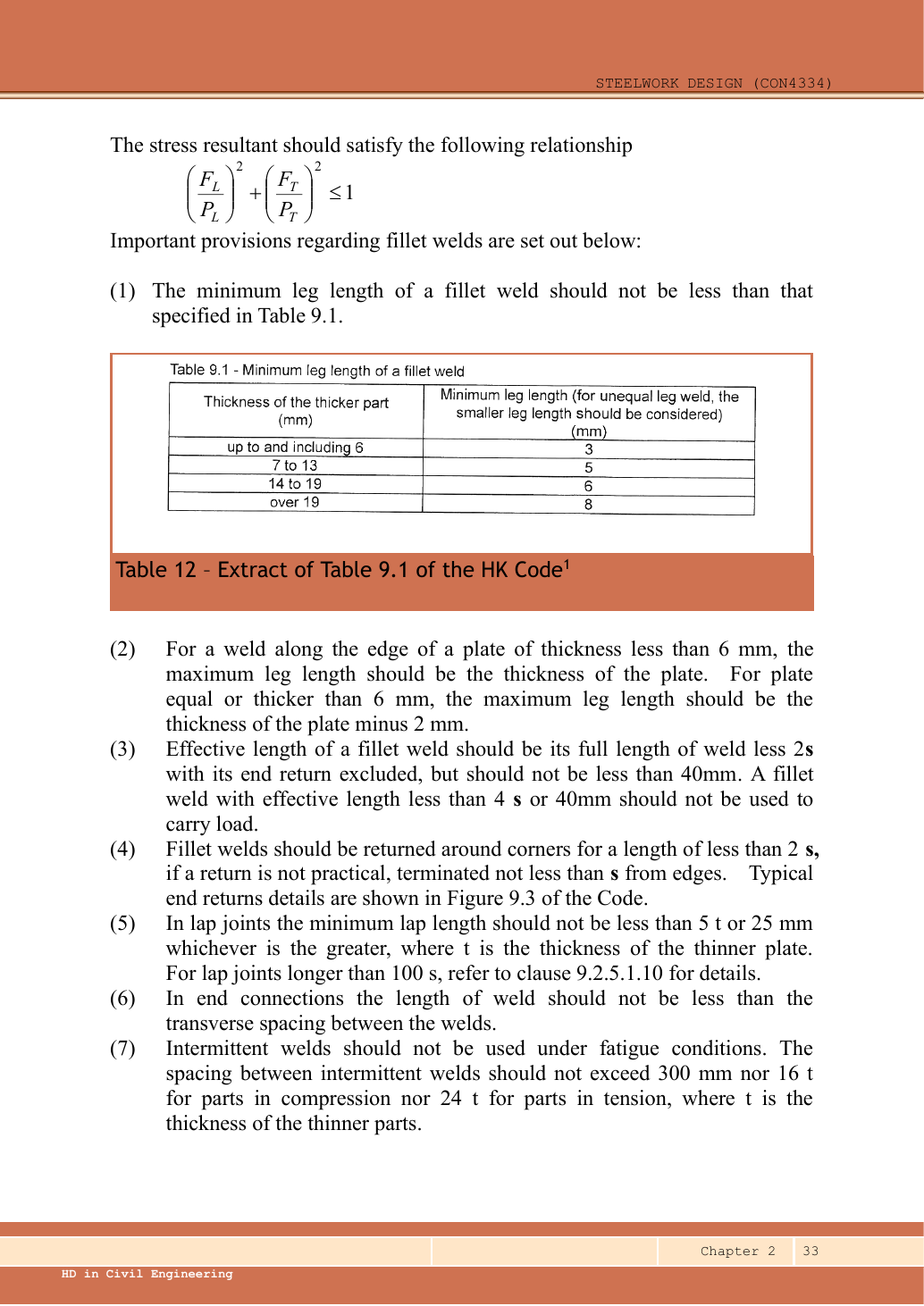
The specified 6 mm weld passes the stated strength calculation but violates the supplied minimum-size table for the 24 mm thicker part. A corrected design uses 8 mm; for the four-longitudinal-run alternative provide 160 mm physical length per run per half. This is an explicit redesign, not the answer to a compliant 6 mm connection.
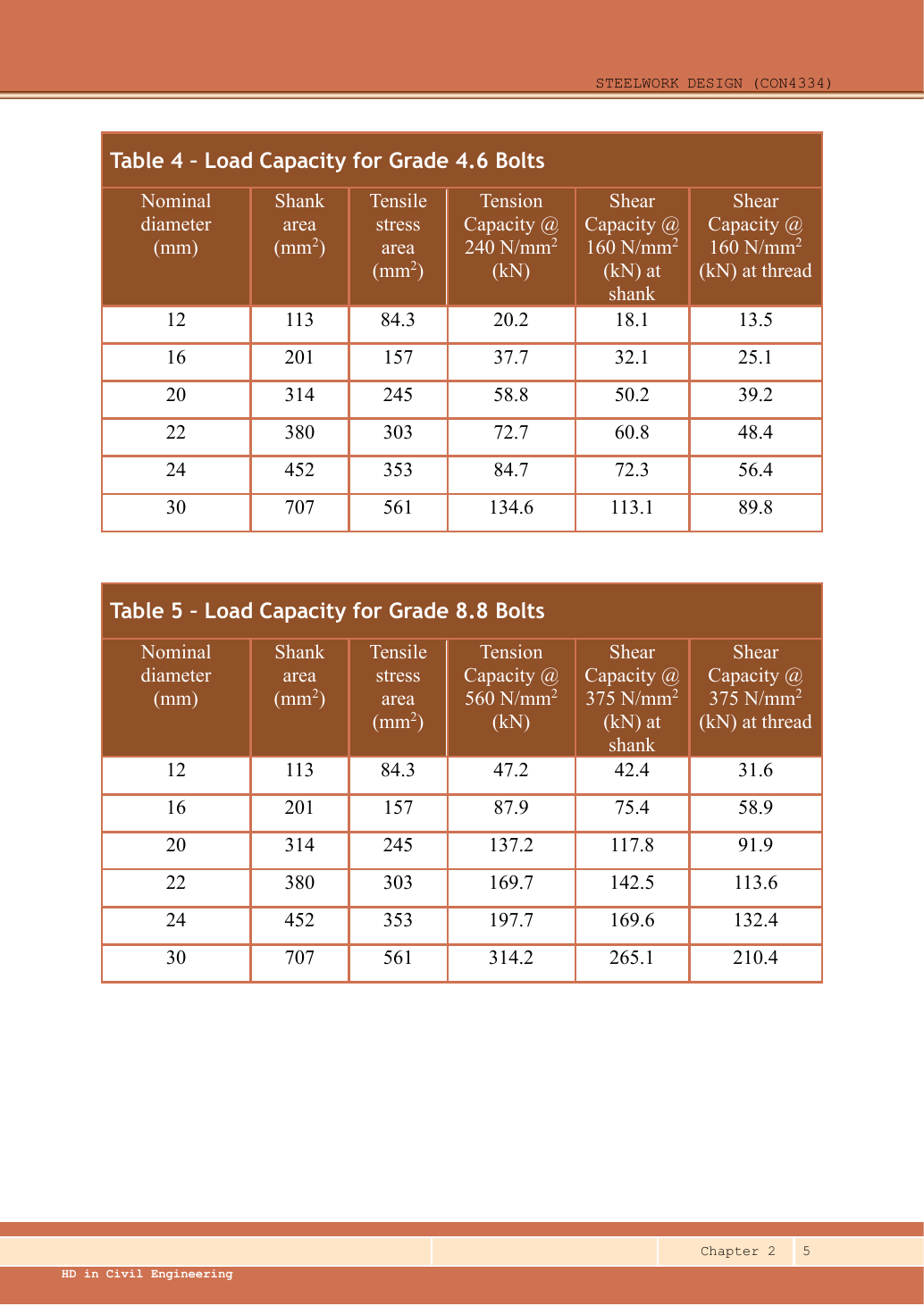
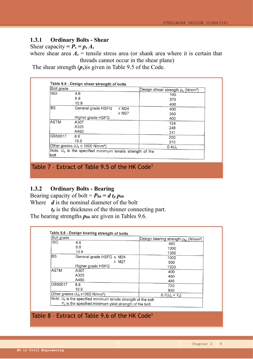
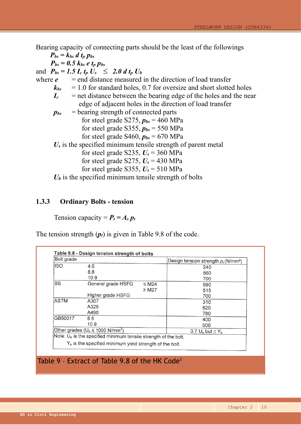
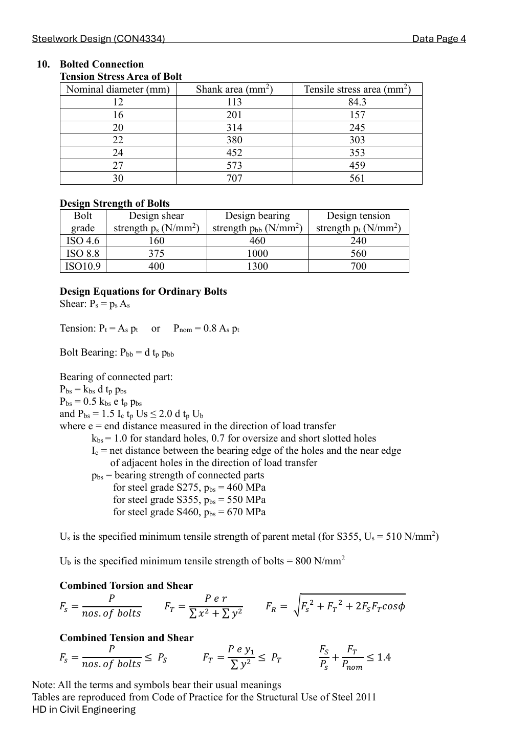
Grade 8.8: shear strength ps = 375, bolt bearing pbb = 1000, ultimate bolt strength Ub = 800 N/mm². S355 plate: pbs = 550, Us = 510 N/mm², Ke = 1.1. Use threaded stress area As for the conservative shear plane, nominal d for bearing, and hole diameter d0 for material removed.
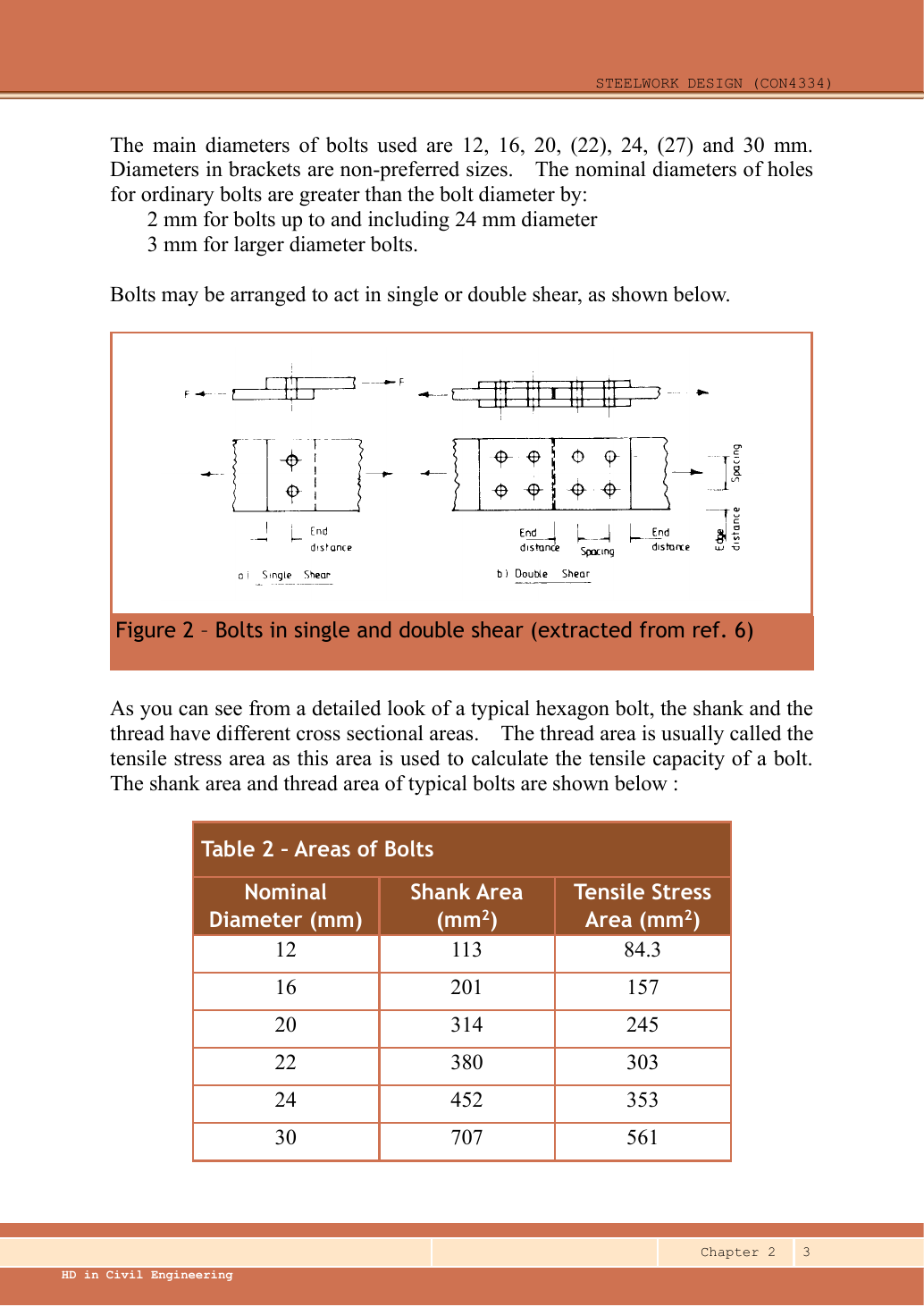
The two symmetric side plates share the total force and moment equally. Work on ONE plate, using bolt coordinates measured from that plate’s bolt-group centroid. A bolt connecting this side plate to its column flange is in single shear.
The two symmetric side plates share the total force and moment equally. Work on ONE plate, using bolt coordinates measured from that plate’s bolt-group centroid. A bolt connecting this side plate to its column flange is in single shear.
Maximum bolt force [10 marks]
Direct shear P/n acts equally on each bolt. Torsion adds a force perpendicular to the radius. At the most loaded corner, its vertical component adds to direct shear; calculate both components before the resultant.
Direct shear P/n acts equally on each bolt. Torsion adds a force perpendicular to the radius. At the most loaded corner, its vertical component adds to direct shear; calculate both components before the resultant.
Choose bolt size [10 marks]
Bolt
As (mm²)
Shear (kN)
Strength
M12
84.3
31.613
FAIL
M16
157
58.875
FAIL
M20
245
91.875
PASS
M22
303
113.625
PASS
M24
353
132.375
PASS
M27
459
172.125
PASS
M30
561
210.375
PASS
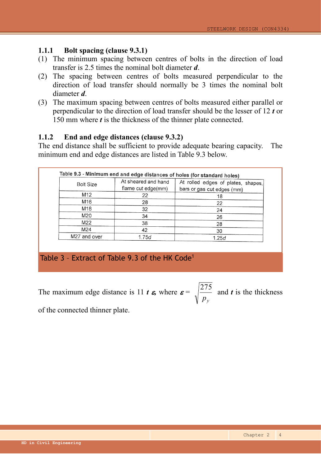
M20 is the smallest candidate passing single shear. Its ordinary end-distance requirement must also be checked: the given end distance is only 30 mm.
If the selected bolt cannot fit the given end distance, no ordinary compliant size exists at that layout: smaller bolts fail shear and larger ones require more edge clearance. Enlarge the end distance or redesign the bolt group. The question excludes plate-strength checks.
Ps=245(375)/1000=91.875kN>0
PASS
Pbb,plate=20(12)(1000)/1000=240kN
The column flange is another connected part. Its actual thickness must also pass; compare the lower bolt-bearing resistance.
Draw the load-transfer stages. Count bolts and shear planes for one stage, then compare all failure modes.
Resolve eccentric forces as vectors. Never add perpendicular components arithmetically.
Use effective weld length and check size limits after strength; “strong enough” does not fix an impossible detail.
Independent practice — invented variant
Invented variant: all applied loads are 10% larger but geometry is unchanged. What scales, and what does not?
Hint
Isolate one load-transfer stage, then distinguish demand from fixed resistance.
Reveal answer
For these linear elastic models, bolt forces and weld force per unit length rise 10%; required strength-only weld throat also rises 10%. Bolt areas, section capacities, effective lengths of already specified welds and detailing limits stay unchanged. Recheck every utilisation.