2022–2024 · Exam-focused route
2023 FT/PTD BQ4 — overhang and LTB
This is the main recent-paper variant to practise after a simply supported beam: support identification changes the entire analysis.
Marks are as printed in the paper; the working is a teaching guide, not an official marking scheme.
An overhang, not a support at A
Vertical bending can trigger sideways motion
A beam has enough local bending resistance. Check whether its compression flange can move sideways and twist.
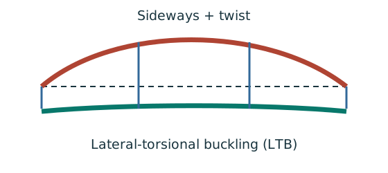
Prediction, then explanation. Adding a valid lateral restraint shortens a stability segment. It need not change the beam’s vertical reaction or moment diagram.
Identify the compressed flange and effective restraints. Calculate the specified slenderness, read buckling strength and compare resistance with the segment demand.
LE and ry use the same length unit. pb uses N/mm²; Sx uses mm³; Mb uses N·mm. mLT is dimensionless.
Scope. Use the specified section class, effective-length branch and loading condition. Load height alone does not prove a destabilizing case.
Check and takeaway. Removing a lateral restraint requires a new segment stability check. The old shorter-segment result cannot establish the longer segment’s adequacy.
Keep load categories separate
A floor carries permanent material and changing occupancy loads. Find the design load for the stated check.
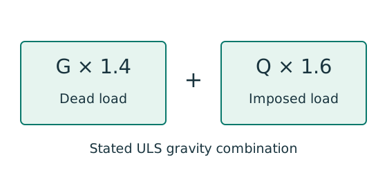
Prediction, then explanation. Increasing imposed load changes its own term. It does not change the dead-load factor or the steel stiffness.
First convert mass to weight where required. Next collect G and Q in compatible units. Apply the combination specified by the course problem.
G is characteristic dead load; Q is characteristic imposed load. Wu is the design load for this course gravity combination.
Scope. This combination is not universal. Use the specified service load for deflection and the stated factors for other standards or cases.
Check and takeaway. Illustration: G = 10 kN and Q = 5 kN give 22 kN. Factoring their sum by one guessed factor loses the distinction.
Apply the reasoning to this section’s data and conditions
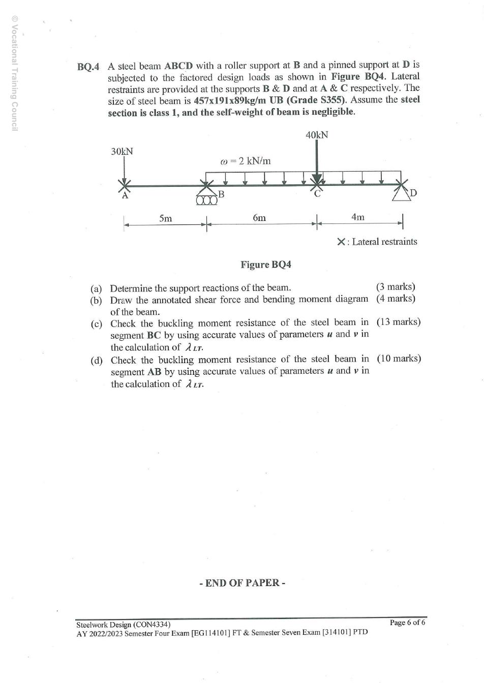
The roller is at B and the pin at D.
A is a free vertical tip with a lateral-restraint cross; C is another lateral restraint.
Coordinates from A are 0, 5, 11 and 15 m.
Factored downward loads: 30 kN at A, 40 kN at C, and 2 kN/m only from B to D.
Self-weight is negligible.
The S355 457 × 191 × 89 UB is given as Class 1.
Physical interpretation and limits
The left overhang behaves like a diving board sticking beyond its support.
A downward force at its free tip creates hogging at B.
The cross at A stops sideways movement.
It does not lift the beam up, so there is no vertical reaction at A.
BQ4(a) — support reactions [3 marks]
Balance the isolated beam
Find the two vertical reactions before calculating internal shear or moment.
Prediction, then explanation. Move the same load toward B. Reaction B increases because the load has a larger moment arm about A.
Take moments about A. Reaction A has zero lever arm there. Then use vertical force balance to find reaction A.
P, RA and RB are forces in kN. L is support spacing and a is load position, both in m.
Scope. These expressions describe one point load on a simply supported beam. Add other loads through equilibrium; keep their actual positions.
Check and takeaway. Illustration: P = 60 kN, L = 6 m and a = 2 m give RB = 20 kN and RA = 40 kN.
Apply the reasoning to this section’s data and conditions
Take counter-clockwise moments as positive about B.
The left-tip force rotates in the opposite sense to loads on the right.
The 20 kN UDL resultant is at the midpoint of BD, 5 m to the right of B.
Check total upward reaction 90 kN against the total downward load 90 kN.
BQ4(b) — annotated SFD and BMD [4 marks]
A cut reveals the internal actions
Find where the beam moment is largest. A large load arrow alone does not locate that point.
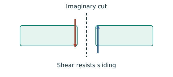
Prediction, then explanation. Under a uniform downward load, shear falls steadily. Moment reaches a stationary value where shear becomes zero.
Balance the forces on the cut piece to get V. Balance their moments about the cut to get M. Evaluate each load region separately.
x and L use m; w uses kN/m; V uses kN; M uses kN·m. These lines apply before any point load.
Scope. A point load adds a shear jump. A concentrated couple adds a moment jump. Check load points, supports and overhang roots too.
Check and takeaway. A UDL gives a sloping shear line and a curved moment line. A flat moment diagram therefore cannot represent a loaded UDL region.
Apply the reasoning to this section’s data and conditions
Choose positive sagging moment.
On AB, x is measured from A; on BC, s is measured from B; on CD, t is measured from C.
Keep these origins explicit.
At B and C the bending moment is continuous, even though shear jumps.
The BD moment diagram changes sign within BC.
Solve the quadratic and choose the root that lies inside the 6 m segment.
The other root is outside and has no physical relevance here.
Shear is positive throughout BC, so moment increases from −150 to +60.
The largest absolute moment is 150 kN·m at B.
CD decreases from +60 to zero.
AB is a straight negative triangle because it has no UDL.
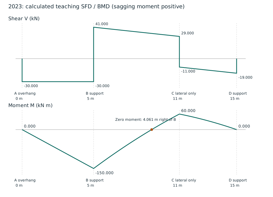
Calculated SFD/BMD: B is the vertical support at 5 m, the zero-moment point is 4.060718 m right of B.
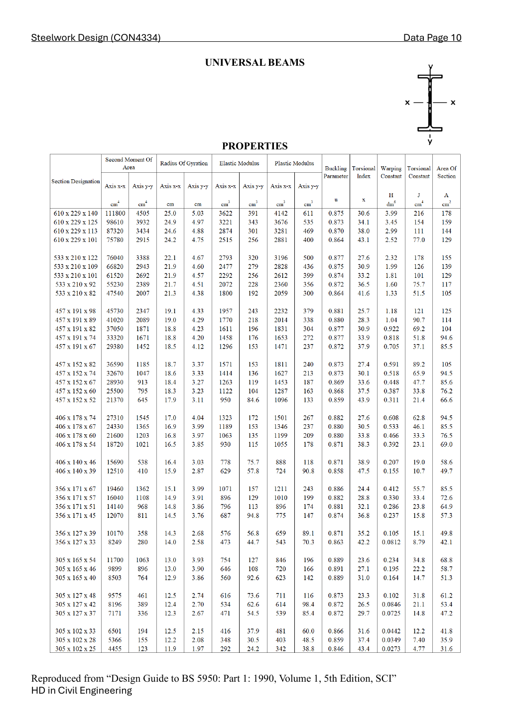
Look up the exact UB row
A table value has conditions
Find a design property without mixing a row, column or standard from a different case.
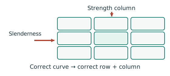
Prediction, then explanation. A different flange thickness can select a lower design strength even when the steel grade name remains unchanged.
Match the complete section designation. Read the relevant axis and unit. For strength tables, select material, thickness and curve before interpolating.
Given values come from the question. Lookup values come from a named table. Assumed values require an explicit condition.
Scope. A missing row or omitted restraint cannot be recovered from a schematic’s scale. Keep the result conditional when required data are absent.
Check and takeaway. Record the table, row, column and unit beside the substitution. That makes a later check possible.
Apply the reasoning to this section’s data and conditions
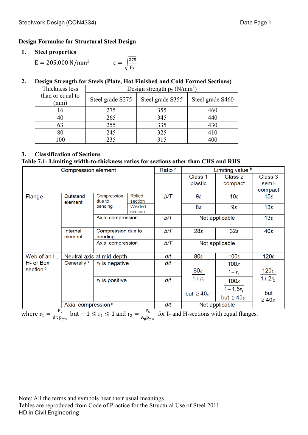
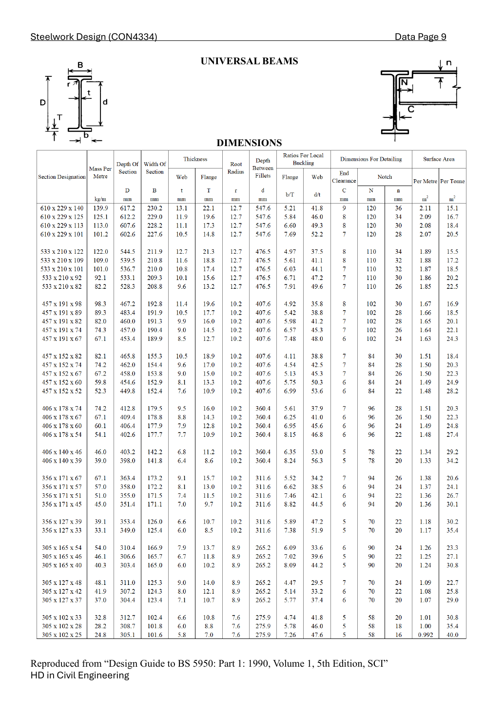
BQ4(c) — segment BC [13 marks]
Moment shape matters within one segment
Represent a nonuniform moment distribution in the applicable member-buckling equation.
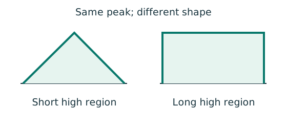
Prediction, then explanation. Two segments can have equal peak moment but different distributions. Their equivalent moment factors can therefore differ.
Evaluate moments from the true whole-beam analysis at the required positions. Apply the exact table’s weights, signs and lower bound.
mLT is an LTB factor. mx and my belong to the specified flexural checks. They are not interchangeable.
Scope. Some rules use magnitudes; others require signed ordinates. A factor does not reduce the actual moment used in a local section check.
Check and takeaway. Measure quarter points from the segment start, not automatically from the beam’s left support.
Use the same mechanism: Vertical bending can trigger sideways motion. Adding a valid lateral restraint shortens a stability segment. It need not change the beam’s vertical reaction or moment diagram.
Use the same mechanism: A cut reveals the internal actions. Under a uniform downward load, shear falls steadily. Moment reaches a stationary value where shear becomes zero.
Apply the reasoning to this section’s data and conditions
Evaluate the BC formula at s = 1.5, 3 and 4.5 m from B.
These correspond to global x = 6.5, 8 and 9.5 m from A.
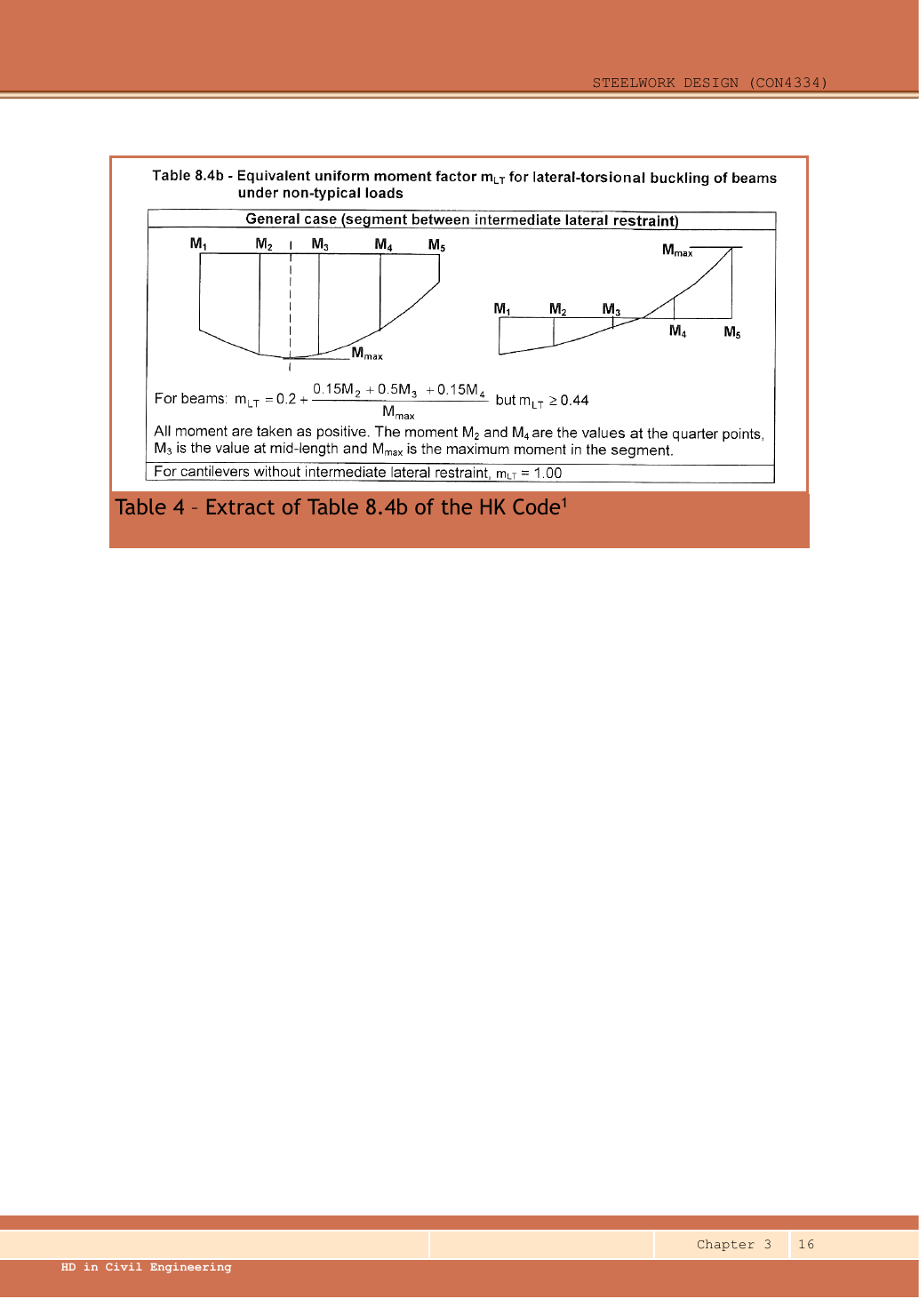
Use the moments at one-quarter, one-half and three-quarters of THIS restrained segment.
They are not necessarily at load points.
Evaluate the actual quadratic bending diagram including the UDL.
Use absolute magnitudes in the quarter-point expression and compare with the maximum absolute moment in the segment.
| Quarter point coordinate | Moment (kN·m) |
|---|---|
Use millimetres in slenderness.
The section table supplies the minor-axis radius of gyration, buckling parameter and torsional index.
The given Class 1 section has a plastic-section factor of one.
These quantities change when the section changes.
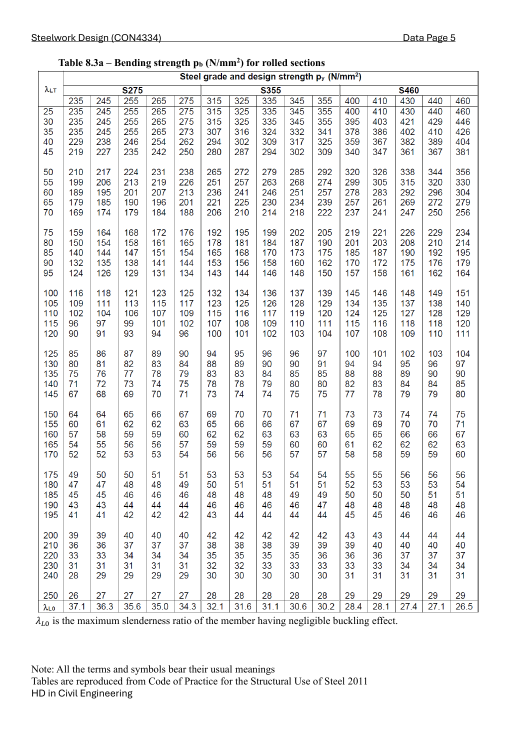
Choose Data File p.5, Table 8.3, 345 N/mm² column.
Interpolate between the two surrounding slenderness rows in the same design-strength column.
Do not mix columns.
Buckling strength times plastic modulus gives moment resistance.
Convert the tabulated cubic centimetres to cubic millimetres, then newton-millimetres to kilonewton-metres.
The stated effective-length model passes this LTB check.
BQ4(d) — cantilever AB, conditional branches [10 marks]
Use the same mechanism: Moment shape matters within one segment. Two segments can have equal peak moment but different distributions. Their equivalent moment factors can therefore differ.
Use the same mechanism: Vertical bending can trigger sideways motion. Adding a valid lateral restraint shortens a stability segment. It need not change the beam’s vertical reaction or moment diagram.
Use the same mechanism: A cut reveals the internal actions. Under a uniform downward load, shear falls steadily. Moment reaches a stationary value where shear becomes zero.
Apply the reasoning to this section’s data and conditions
AB is a cantilever segment without an intermediate lateral restraint.
The course cantilever moment-factor rule is mLT = 1, even though its bending diagram is triangular.
The simply supported end-moment factor is not applicable.
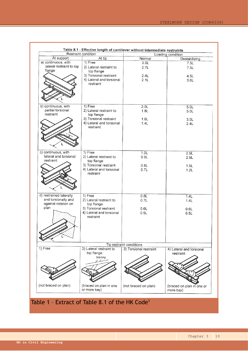
Course Table 8.1: cantilever effective length.
Read support row, tip condition and loading column together.
Branch 1: continuous support with lateral AND torsional restraint (row c), tip lateral restraint to top flange (tip 2), NORMAL loading.
Table value 0.9L gives 4,500 mm.
Use millimetres in slenderness.
The section table supplies the minor-axis radius of gyration, buckling parameter and torsional index.
The given Class 1 section has a plastic-section factor of one.
These quantities change when the section changes.
Choose Data File p.5, Table 8.3, 345 N/mm² column.
Interpolate between the two surrounding slenderness rows in the same design-strength column.
Do not mix columns.
Buckling strength times plastic modulus gives moment resistance.
Convert the tabulated cubic centimetres to cubic millimetres, then newton-millimetres to kilonewton-metres.
The stated effective-length model passes this LTB check.
Branch 2: continuous support with lateral restraint to top flange only (row a), the same tip condition 2 and NORMAL loading.
Table value 2.7L gives 13,500 mm.
Use millimetres in slenderness.
The section table supplies the minor-axis radius of gyration, buckling parameter and torsional index.
The given Class 1 section has a plastic-section factor of one.
These quantities change when the section changes.
Choose Data File p.5, Table 8.3, 345 N/mm² column.
Interpolate between the two surrounding slenderness rows in the same design-strength column.
Do not mix columns.
Buckling strength times plastic modulus gives moment resistance.
Convert the tabulated cubic centimetres to cubic millimetres, then newton-millimetres to kilonewton-metres.
The stated effective-length model fails this LTB check.
One branch passes and one fails.
Therefore write the chosen table row/column and assumption in an exam answer.
Do not claim the given lateral crosses prove an unconditional pass.
A destabilizing loading case needs its own table column and recalculation.
Result and concise exam wording
Use the same mechanism: Balance the isolated beam. Move the same load toward B. Reaction B increases because the load has a larger moment arm about A.
Use the same mechanism: Vertical bending can trigger sideways motion. Adding a valid lateral restraint shortens a stability segment. It need not change the beam’s vertical reaction or moment diagram.
Apply the reasoning to this section’s data and conditions
Concise exam wording
BC passes its stated branch.
AB needs the cantilever restraint/loading conditions before a unique pass/fail decision; show the chosen conditional branch.
Misconceptions and checks
Use the same mechanism: Balance the isolated beam. Move the same load toward B. Reaction B increases because the load has a larger moment arm about A.
Use the same mechanism: Vertical bending can trigger sideways motion. Adding a valid lateral restraint shortens a stability segment. It need not change the beam’s vertical reaction or moment diagram.
Apply the reasoning to this section’s data and conditions
- Do not put a vertical reaction at A.
- Do not extend the UDL onto AB.
- A triangular cantilever diagram does not justify the simple-span mLT formula.
Procedure for a new variant
Use the same mechanism: Vertical bending can trigger sideways motion. Adding a valid lateral restraint shortens a stability segment. It need not change the beam’s vertical reaction or moment diagram.
Use the same mechanism: A cut reveals the internal actions. Under a uniform downward load, shear falls steadily. Moment reaches a stationary value where shear becomes zero.
Use the same mechanism: A table value has conditions. A different flange thickness can select a lower design strength even when the steel grade name remains unchanged.
Apply the reasoning to this section’s data and conditions
- Mark actual vertical supports and the loaded length.
- Solve reactions, signed diagrams and any contraflexure point.
- For each segment choose the correct beam/cantilever model and restraints.
- Calculate table-based LTB and state unresolved conditions.
Prediction with explained answer — invented variant
Use the same mechanism: Balance the isolated beam. Move the same load toward B. Reaction B increases because the load has a larger moment arm about A.
Apply the reasoning to this section’s data and conditions
Invented variant: the 30 kN load at A is removed.
Find the new reactions and moment at B.
Hint
Repeat moment equilibrium about B.
Answer and reasoning
An unloaded free overhang carries no bending moment in this idealized model.
The reactions change even though the support locations do not.