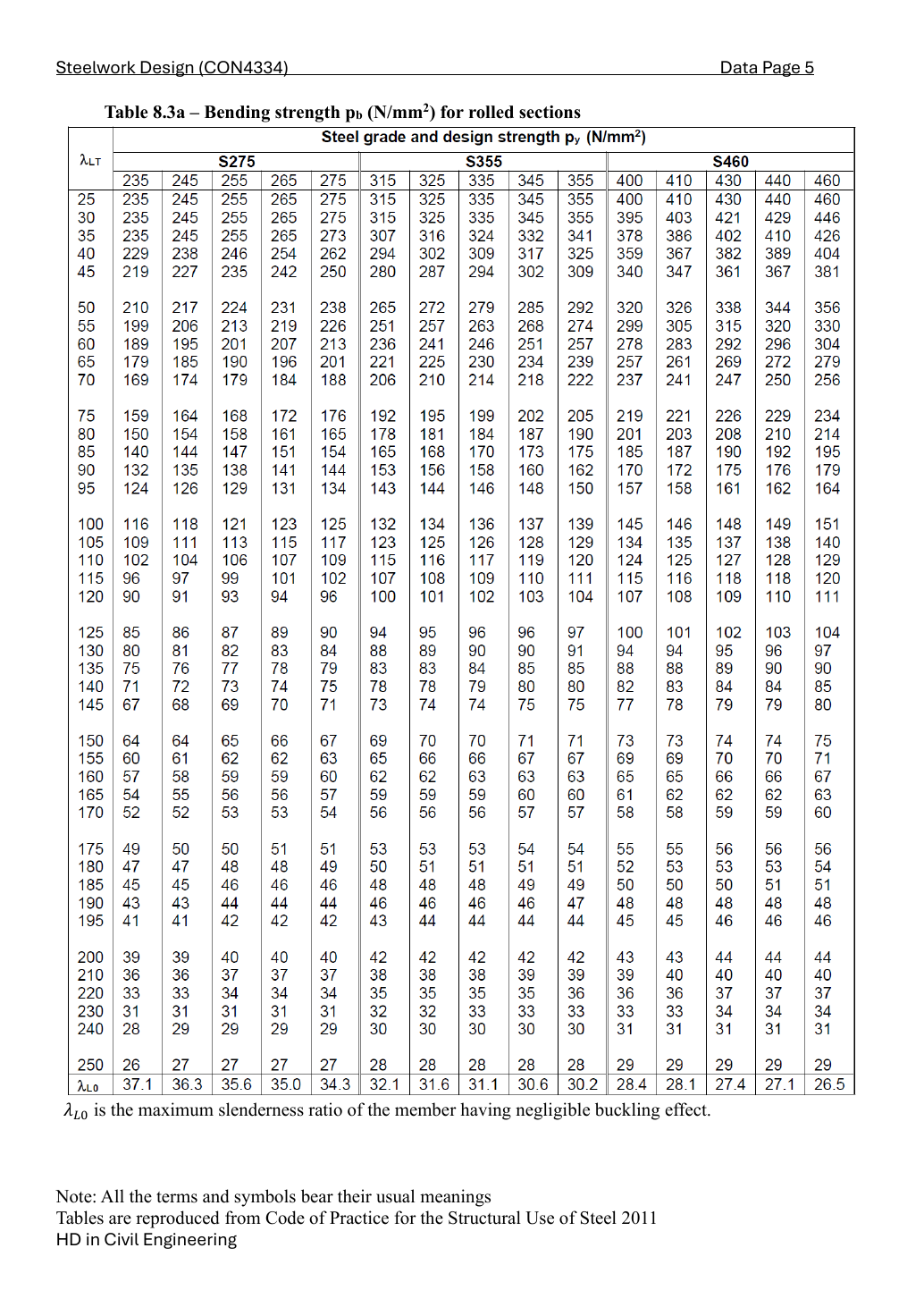
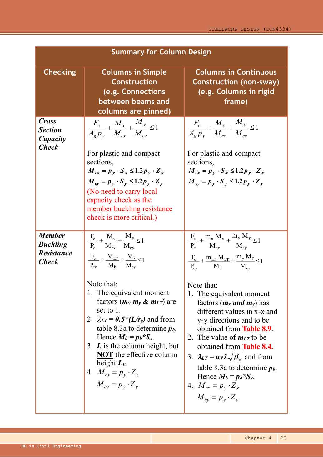
Check 254 × 254 × 89 UC under combined compression and biaxial bending.
Independent teaching answer, not an official solution or marking scheme. Printed marks are retained. Read the source conditions beside each result.
Strategy and prerequisites
Units: 1 kN = 1,000 N; 1 m = 1,000 mm; 1 cm³ = 1,000 mm³; 1 cm⁴ = 10,000 mm⁴. A demand is the load effect; a resistance is what the member can carry. Compare matching units.
Simple explanation — open only if needed
A section is one slice of the column; buckling concerns the whole long member. Three passing checks are needed, just as a strong ruler can still bend sideways when pushed at its ends.
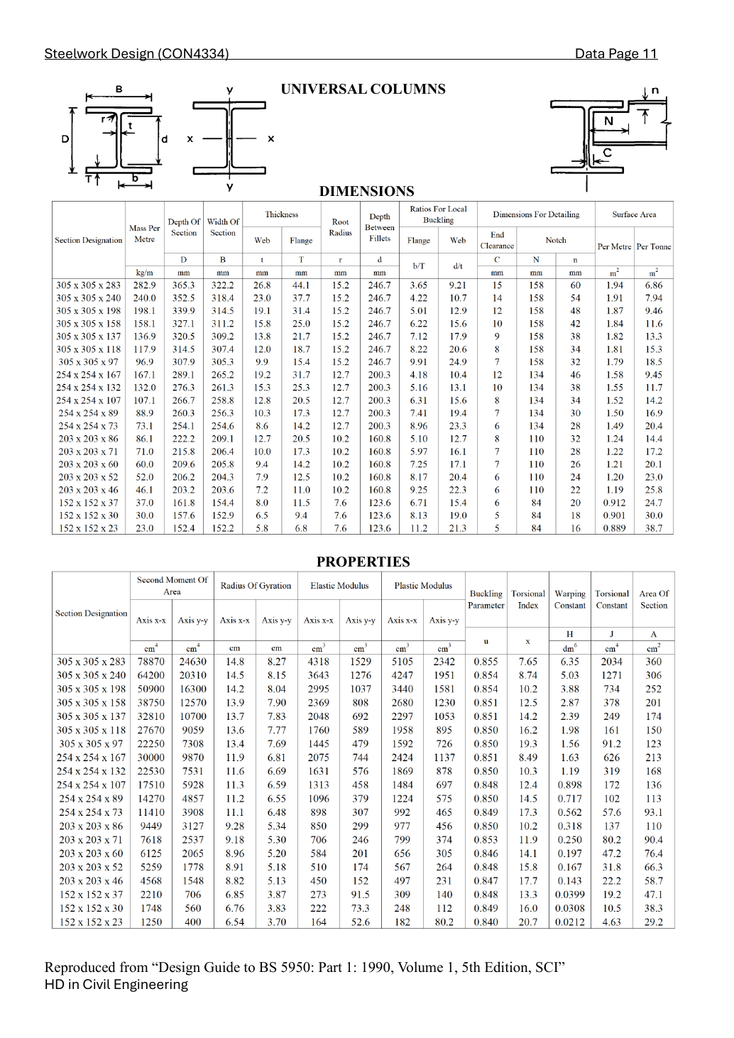
Exact UC row: 254 × 254 × 89. A is gross area, r radius of gyration, Z elastic modulus, S plastic modulus. Convert the tabulated radii from cm to mm; do not use nominal section size as a radius.
T=17.3,t=10.3,d=200.3,rx=112,ry=65.5(mm)
Ag=113×100=11300mm2
Zx=1096,Zy=379,Sx=1224,Sy=575(cm3)
u=0.85,x=14.5,py=345N/mm2
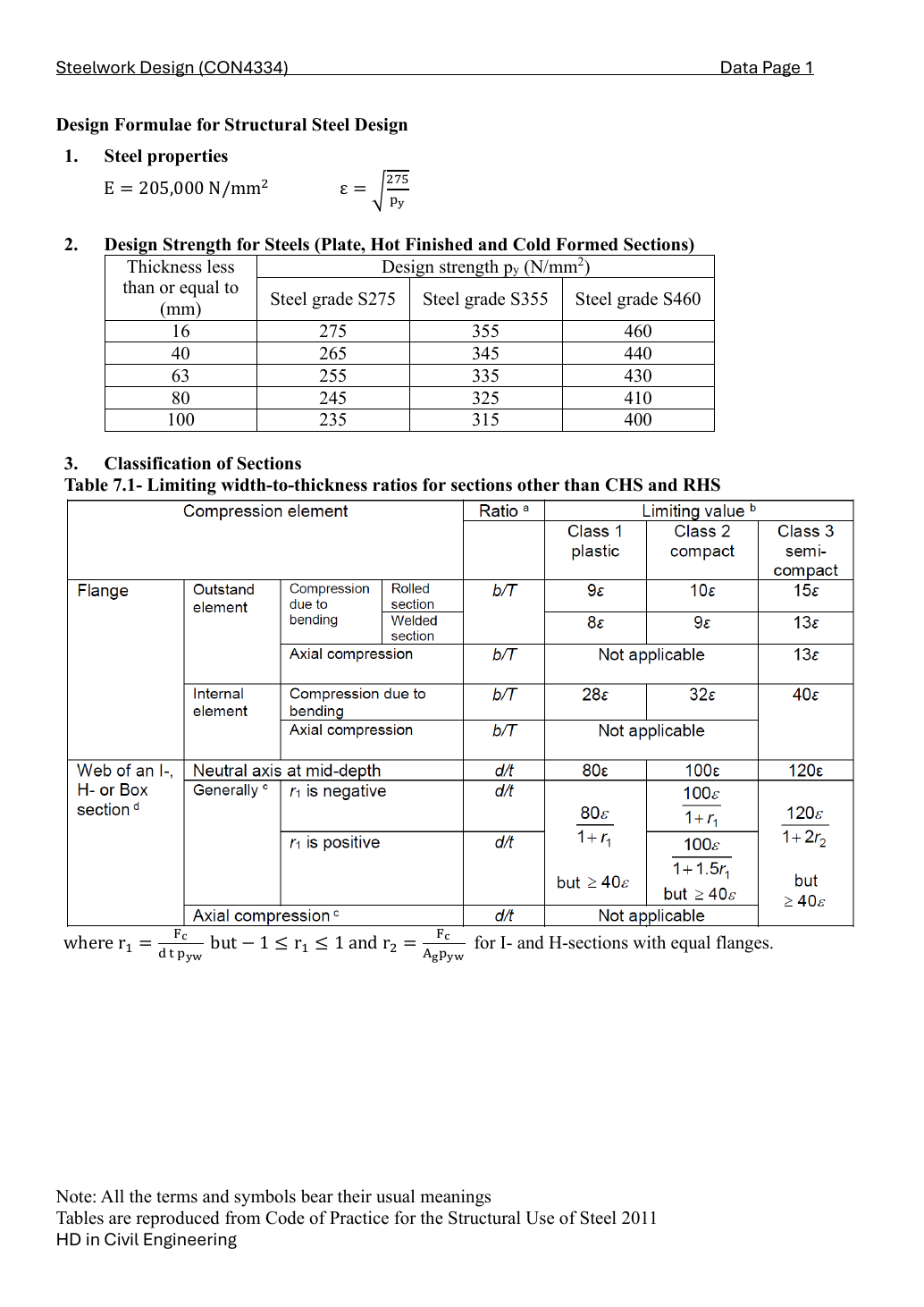
The conservative Class 1 web bound 40ε is valid for the course combined-stress formula because its axial stress parameter is bounded by one. Check the flange separately; use the worse class.
The horizontal x–x axis passes through the web; y–y is vertical on the plan. A vertical drawing offset creates Mx; a horizontal offset creates My. All point forces are axial compression. Opposite offsets give opposite moments. Sum all axial forces, but share the joint moments equally between the equally stiff upper and lower columns.
Force (kN)
Horizontal x (mm)
Vertical y (mm)
150
-100
0
250
200
0
400
0
300
N=1000+150+250+400=1800kN
Mx,j=400(300)/1000=120kNm
My,j=150(−100)/1000+250(200)/1000=35kNm
Mx=∣Mx,j∣/2=60,My=∣My,j∣/2=17.5(kNm)
Mx=1.15(60)=69,My=1.15(17.5)=20.125(kNm)
At a section, combine compression and amplified bending using capped plastic resistances for Class 1/2. All three fractions are dimensionless.
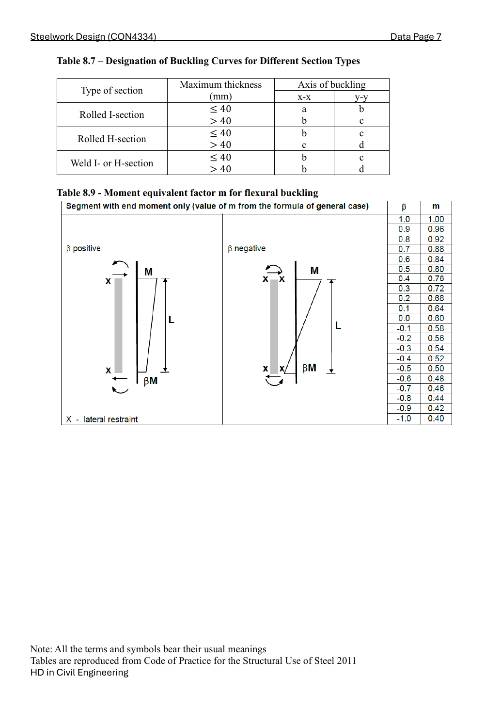
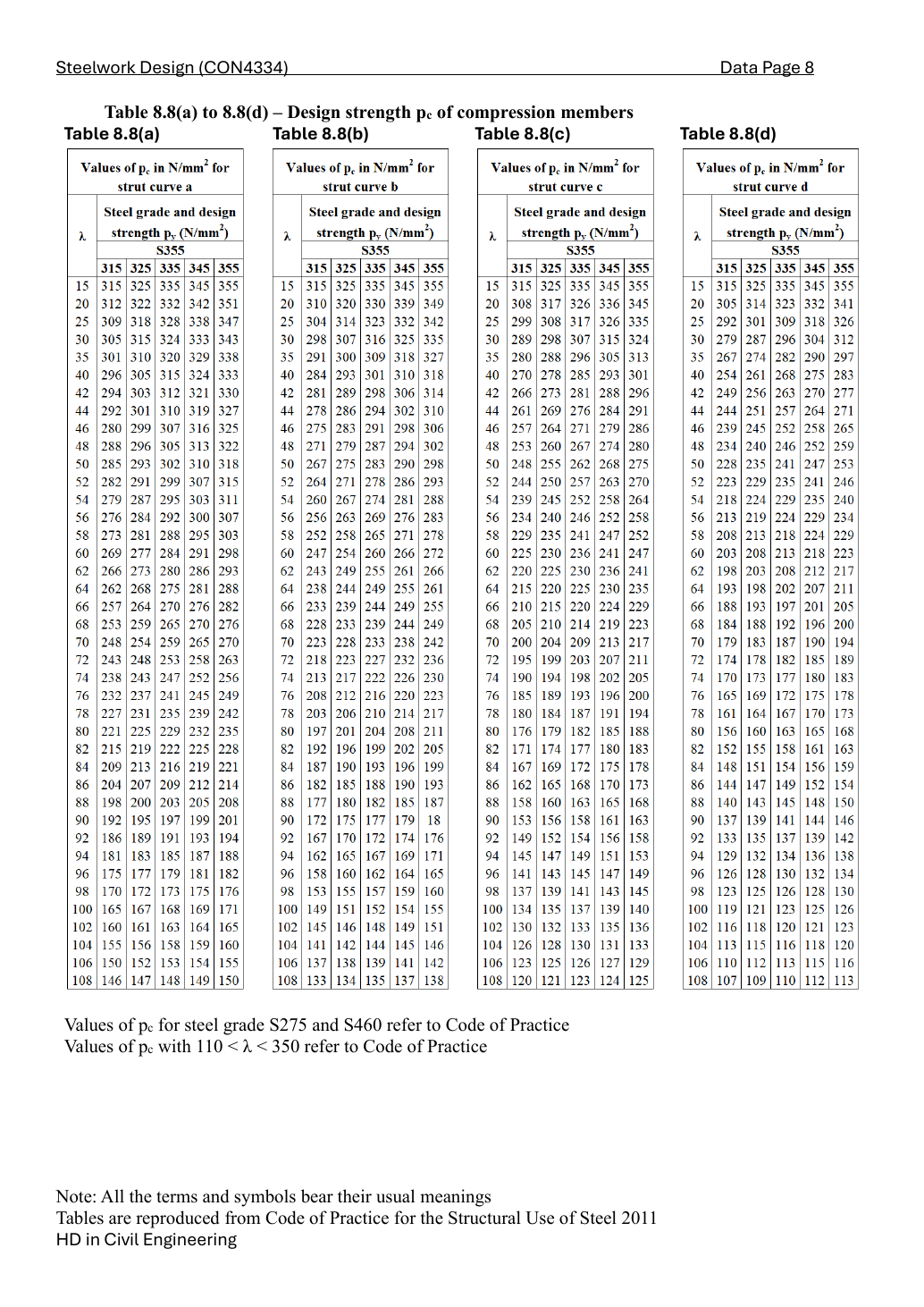
Rolled UC with flange thickness 17.3 mm ≤ 40 mm: curve b about x and curve c about y. Use py = 345 N/mm² in both tables. Linear interpolation uses adjacent slenderness rows, not the nearest section size.
Member interaction uses ELASTIC moduli in the ordinary bending denominators. First equation: smaller axial buckling resistance and amplified moments. Second equation: Pcy and MLT, with first-order minor-axis moment.
Identify the model → axes and actions → class → section → both strut curves → LTB → both member equations. Do not halve axial load, swap x/y moduli, replace the given effective length with the actual height, or amplify MLT twice.
Independent practice — invented variant
Invented variant: axial load increases by 100 kN, moments and class unchanged. How does each utilisation change?
Hint
Only the axial-force numerator changes in this stated variant.