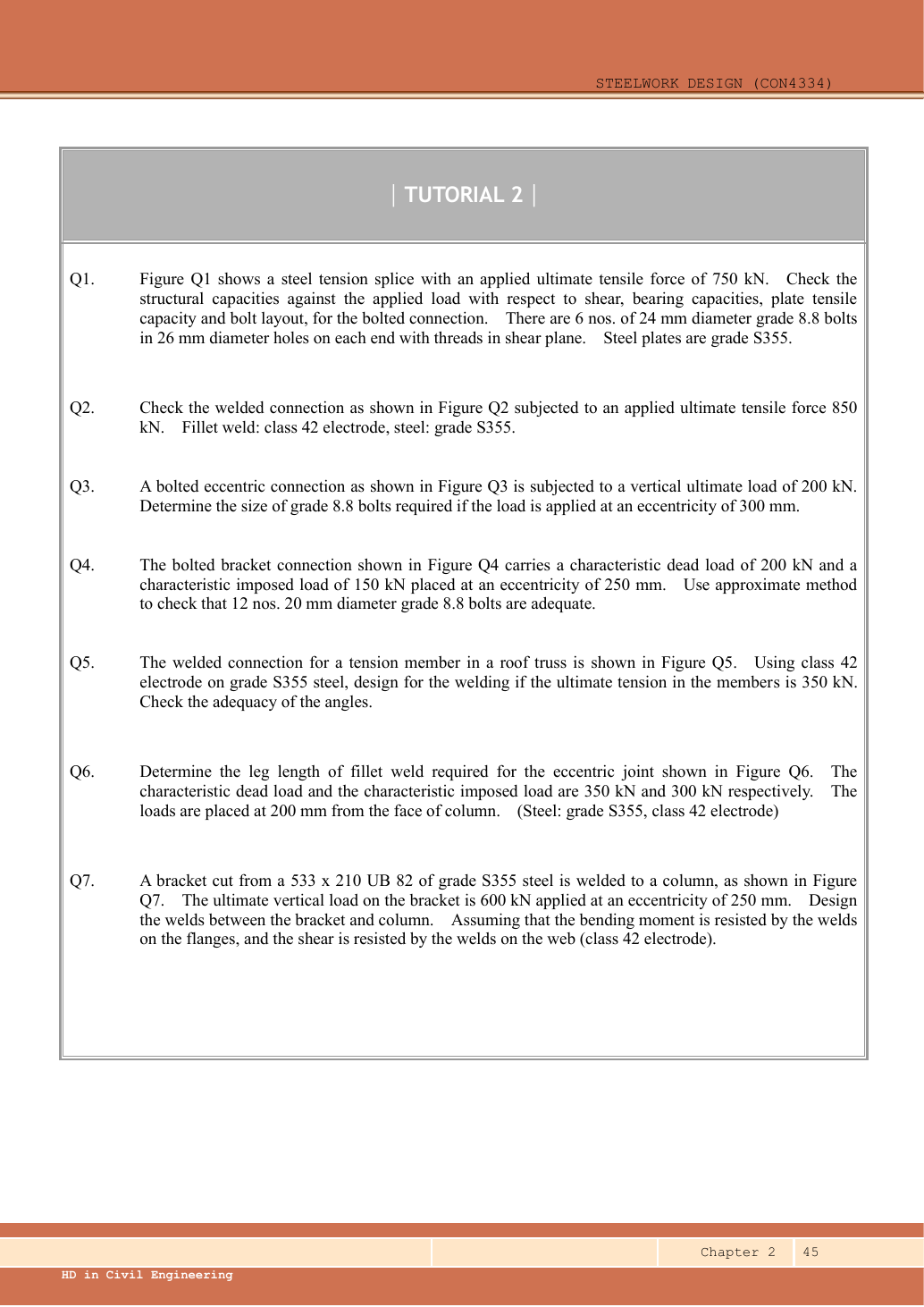
All connection subparts from this paper, including the specified checks and source qualifications.
Independent teaching answer, not an official solution or marking scheme. Printed marks are retained. Read the source conditions beside each result.
Recognise the connection model
Units: 1 kN = 1,000 N; 1 m = 1,000 mm; 1 cm³ = 1,000 mm³; 1 cm⁴ = 10,000 mm⁴. A demand is the load effect; a resistance is what the member can carry. Compare matching units.
A splice transfers axial force through stages. A side-plate bracket creates in-plane torsion. An end-plate bracket creates bolt tension. Identify which picture applies before selecting a formula.
Plate tension [5 marks]
Pu=1.4(150)+1.6(300)=690kN
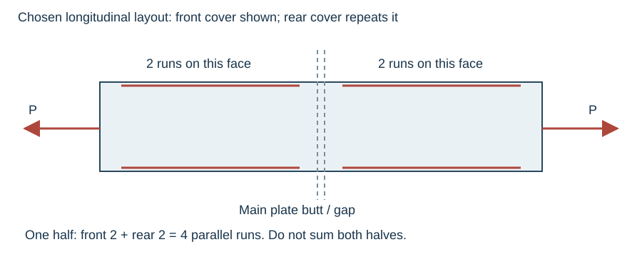
The main plate width is 170 mm; each cover is 120 mm wide, with thicknesses 22 mm and 12 mm respectively. These come from the original width and side-view dimension chains. There are no bolt holes. The two covers act in parallel and each carries half the design tension.
Choose longitudinal welds on both edges of each cover, on each side of the main-plate butt: four parallel weld runs transfer the full force on one half. The other half repeats the load transfer. Count four, not eight, in the capacity of one stage.
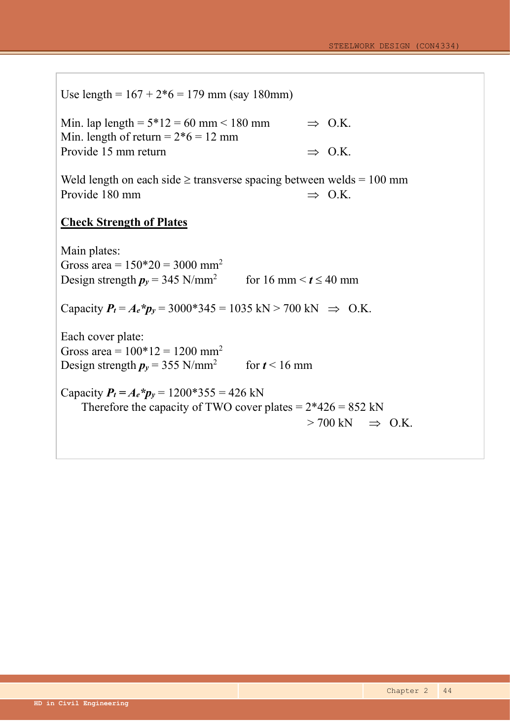
Provide enough effective length for force, minimum effective length and transverse weld spacing; add 2s to each run and round UP to 5 mm. This is a designed arrangement, not an unstated original length.
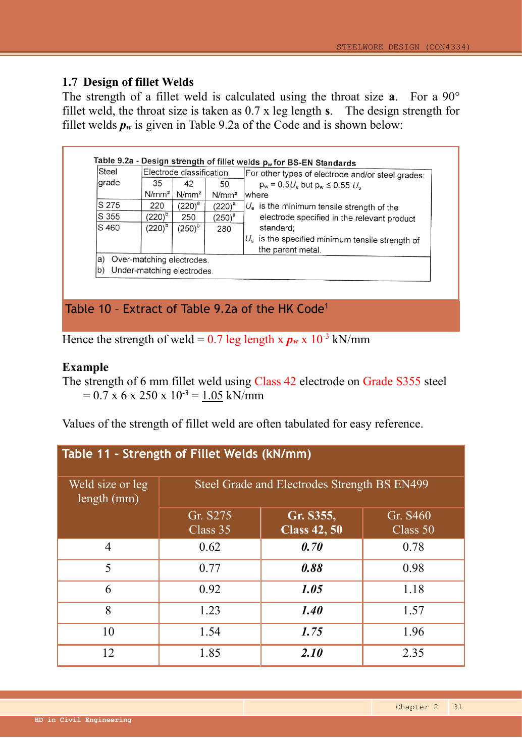
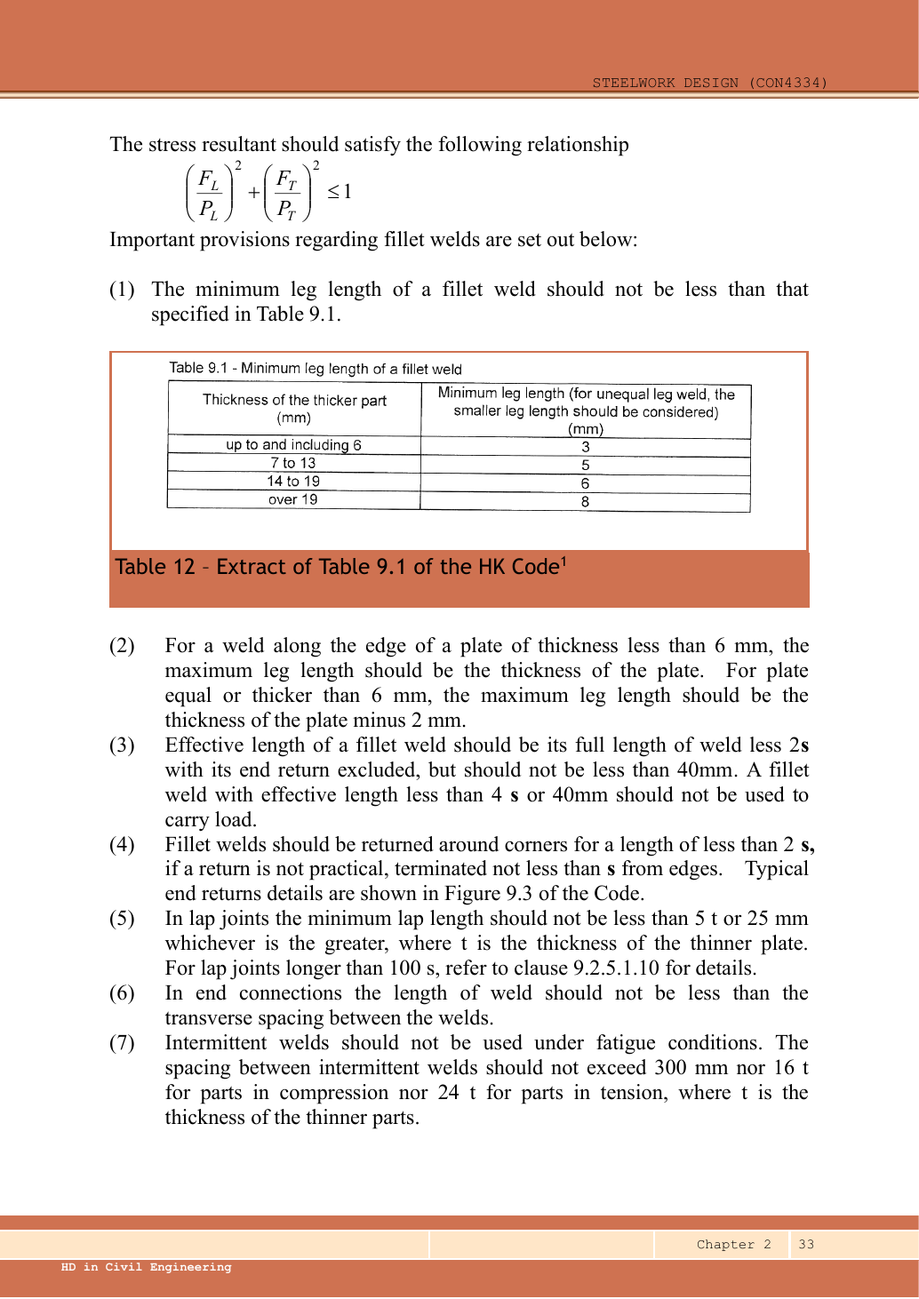
The specified 6 mm weld passes the stated strength calculation but violates the supplied minimum-size table for the 22 mm thicker part. A corrected design uses 8 mm; for the four-longitudinal-run alternative provide 140 mm physical length per run per half. This is an explicit redesign, not the answer to a compliant 6 mm connection.
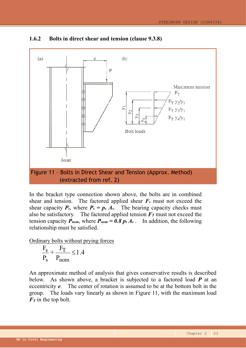
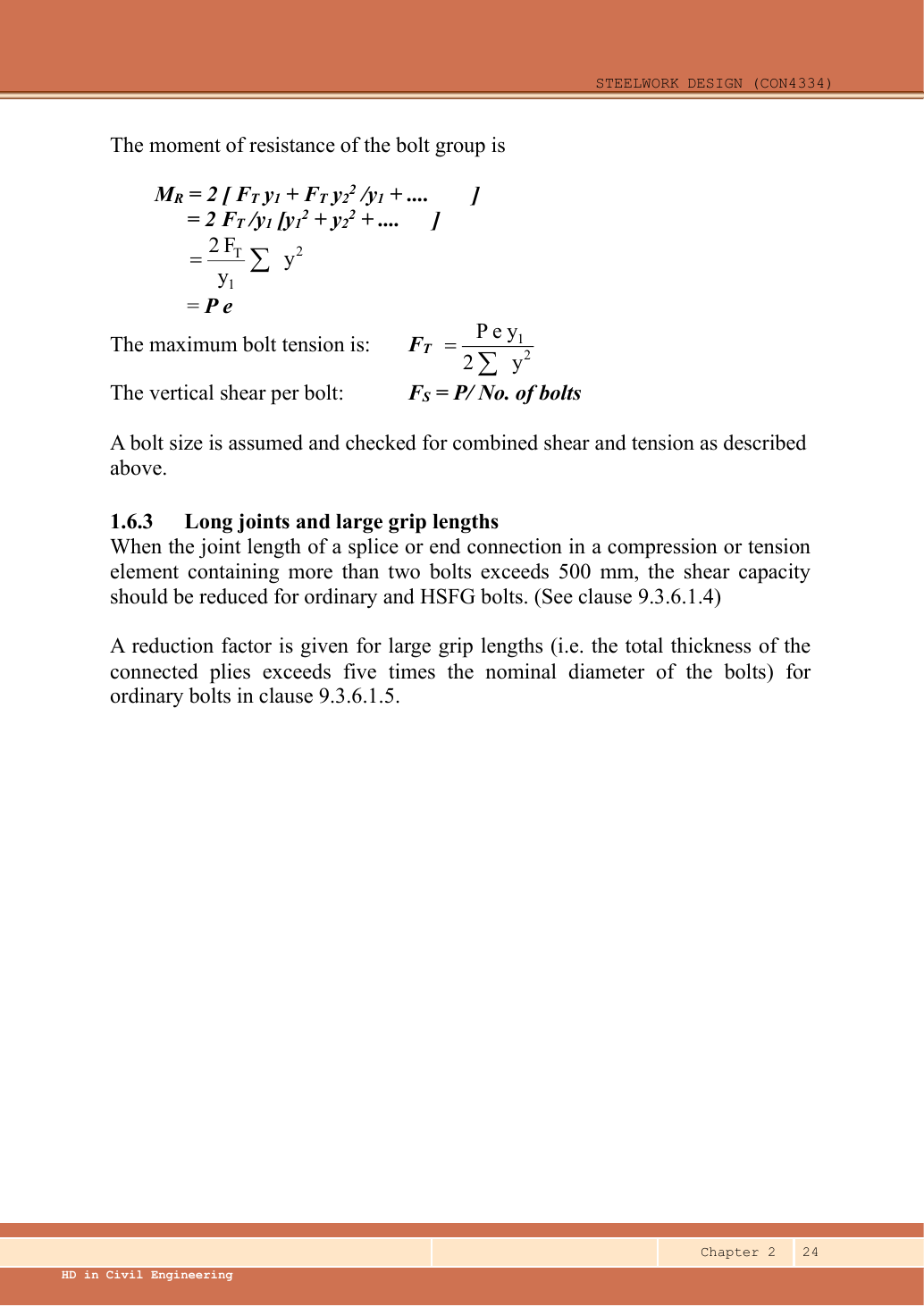
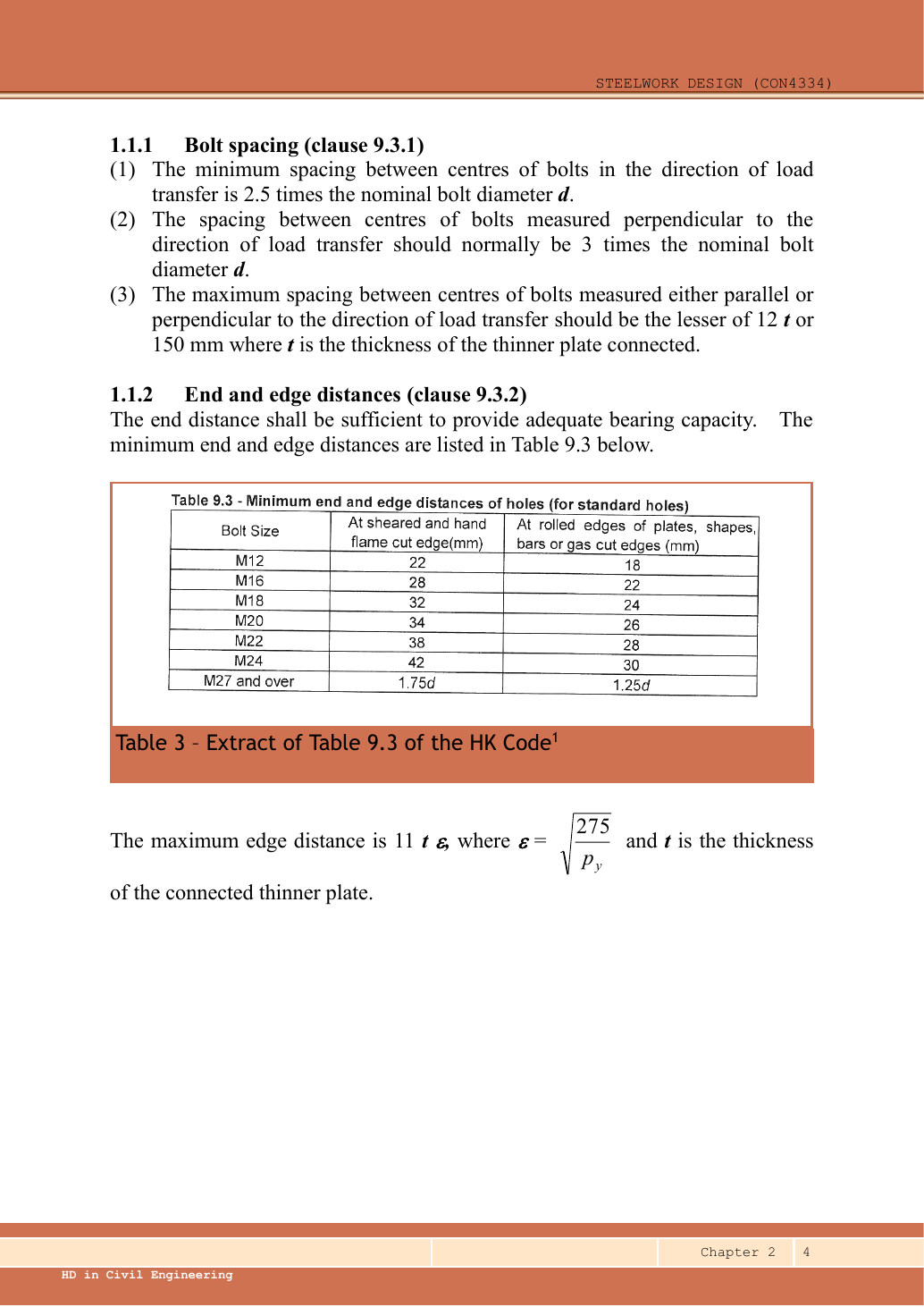
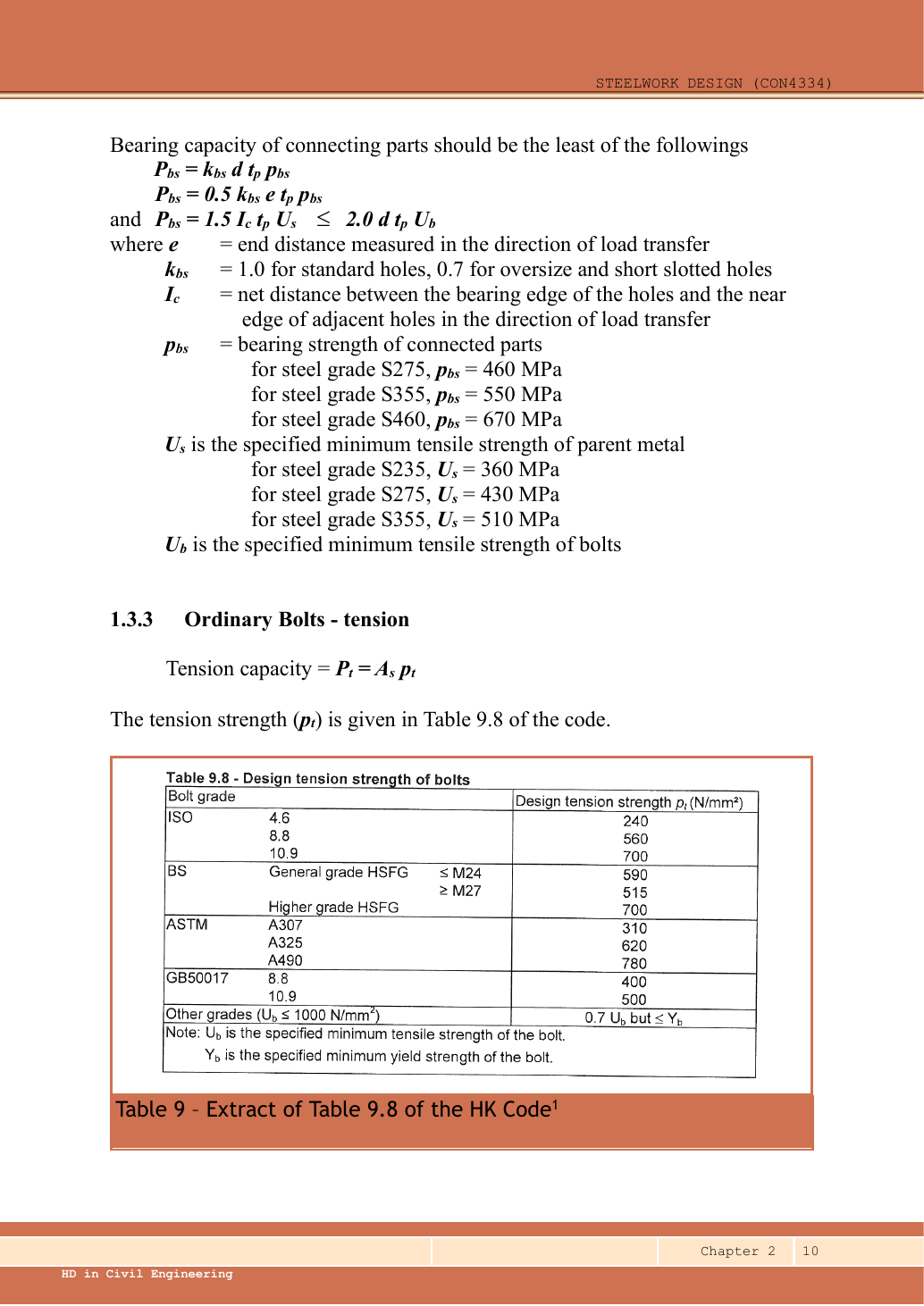
This is an end-plate bracket: the bolts resist vertical shear AND tension caused by overturning, not in-plane bolt-group torsion. Use the lecture’s approximate rotation centre at the BOTTOM BOLT, not the plate edge. Five rows have 70 mm spacing, two bolts per row. The 50 mm below the last bolt is an edge distance, not an extra tension lever arm.
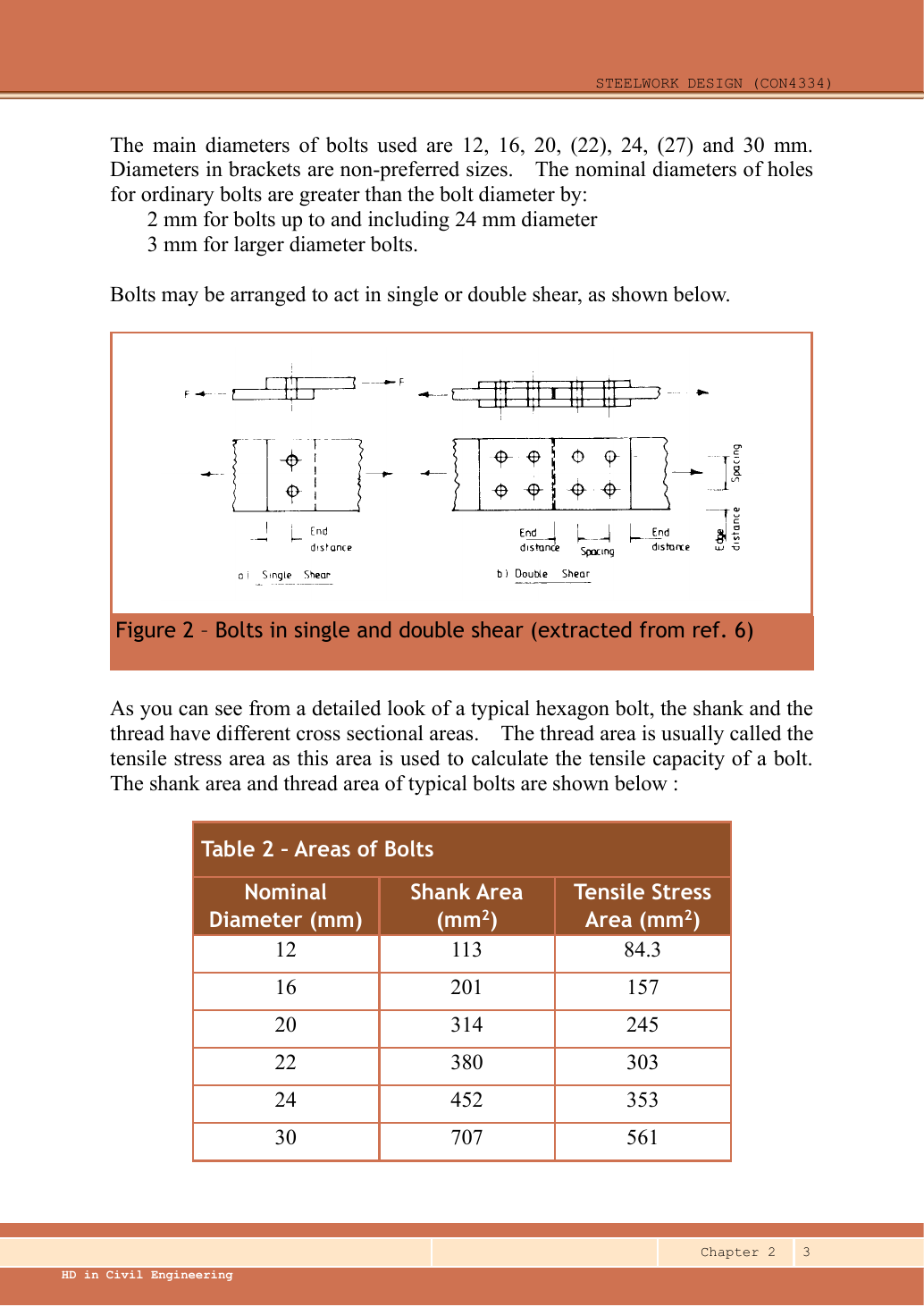
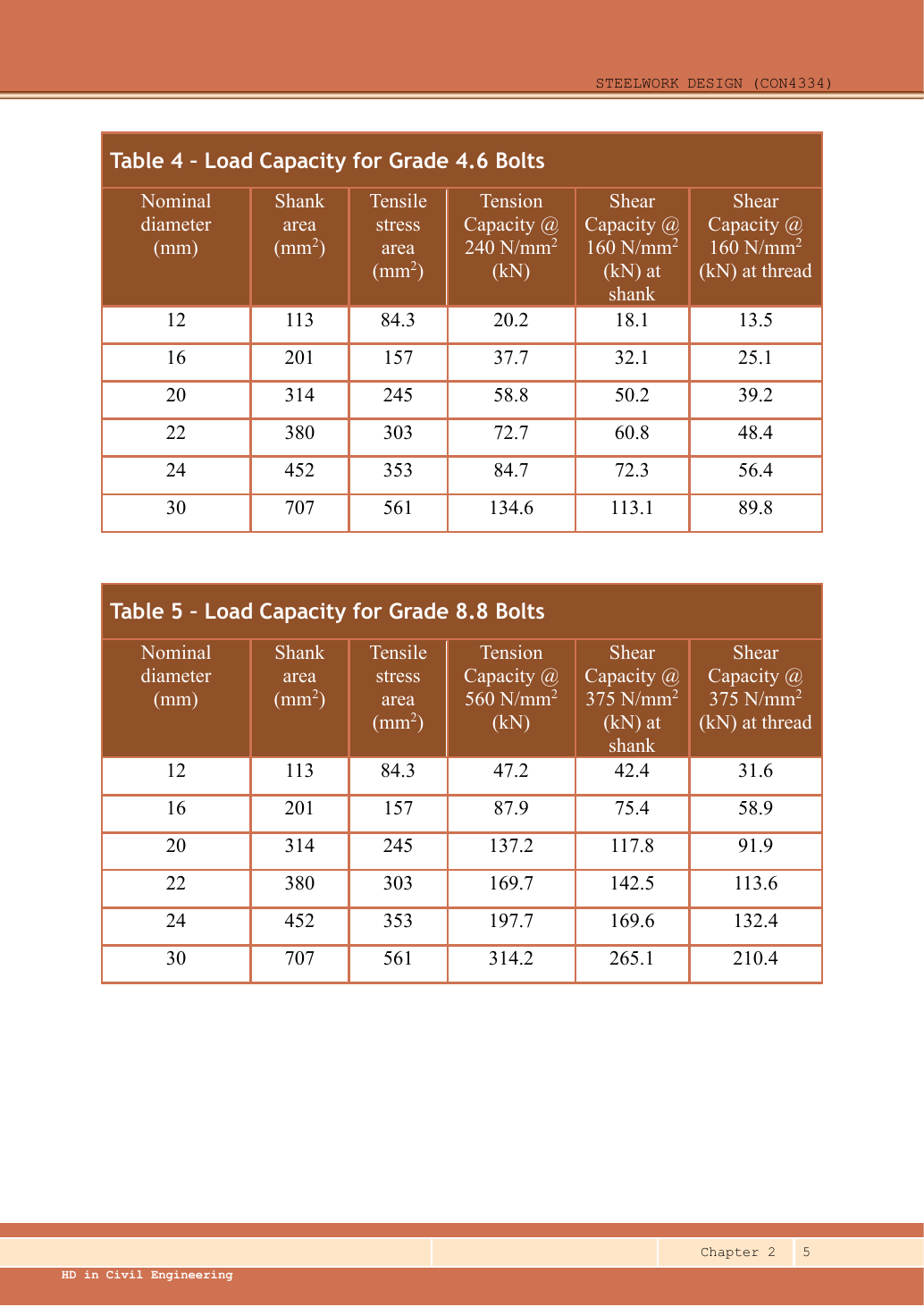
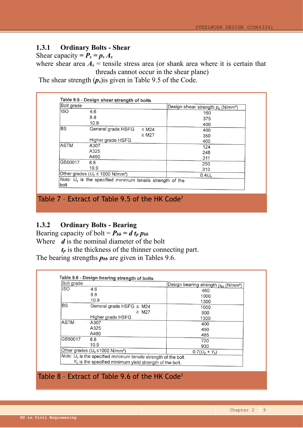
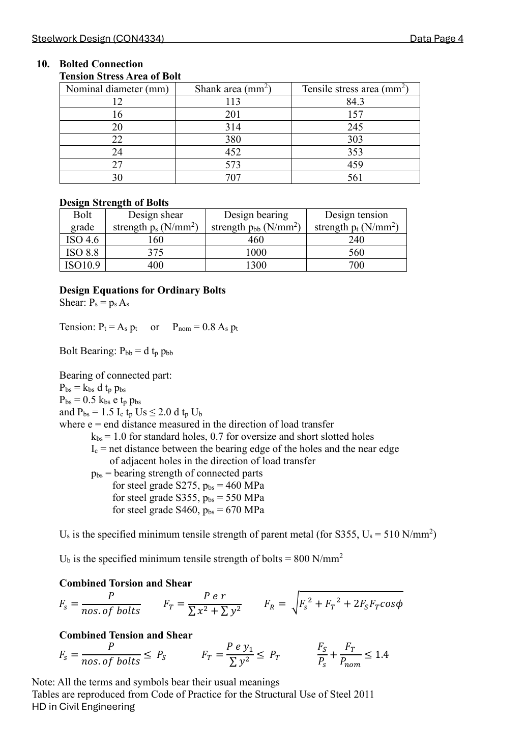
Grade 8.8: shear strength ps = 375, bolt bearing pbb = 1000, ultimate bolt strength Ub = 800 N/mm². S355 plate: pbs = 550, Us = 510 N/mm², Ke = 1.1. Use threaded stress area As for the conservative shear plane, nominal d for bearing, and hole diameter d0 for material removed.
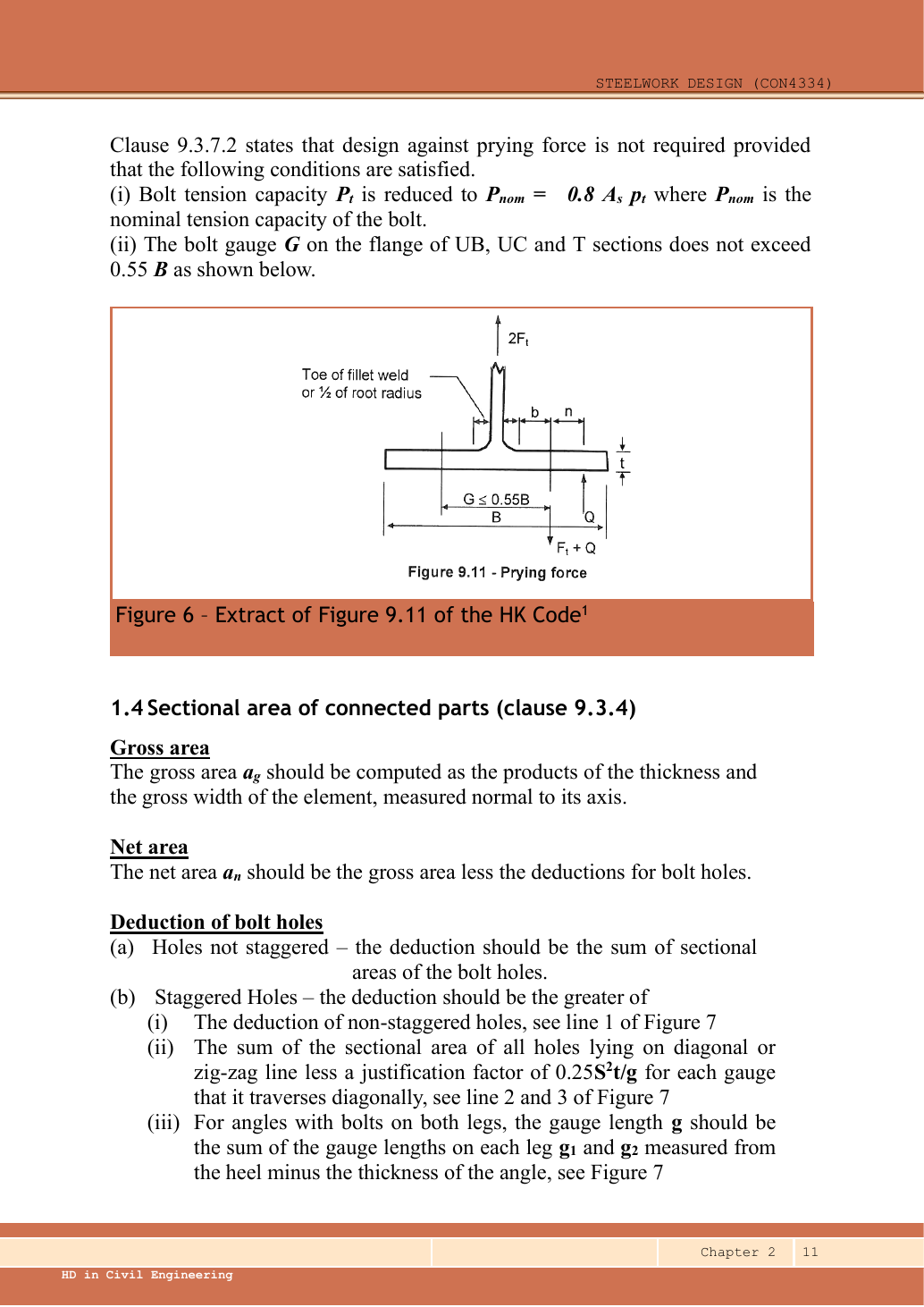
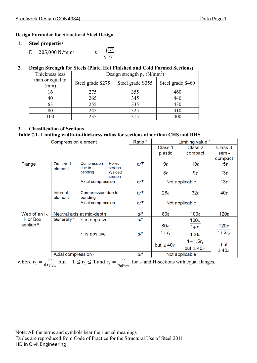
The 305×305×137 UC flange thickness is 21.7 mm, read from the exact UC row. The end plate is the thinner connected part. For ordinary-bolt no-prying treatment, the missing transverse bolt gauge must not exceed 0.55B = 0.55(309.2) = 170.06 mm.
Grade 8.8: shear strength ps = 375, bolt bearing pbb = 1000, ultimate bolt strength Ub = 800 N/mm². S355 plate: pbs = 550, Us = 510 N/mm², Ke = 1.1. Use threaded stress area As for the conservative shear plane, nominal d for bearing, and hole diameter d0 for material removed.
The 305×305×137 UC flange thickness is 21.7 mm, read from the exact UC row. The end plate is the thinner connected part. For ordinary-bolt no-prying treatment, the missing transverse bolt gauge must not exceed 0.55B = 0.55(309.2) = 170.06 mm.
Draw the load-transfer stages. Count bolts and shear planes for one stage, then compare all failure modes.
Resolve eccentric forces as vectors. Never add perpendicular components arithmetically.
Use effective weld length and check size limits after strength; “strong enough” does not fix an impossible detail.
Independent practice — invented variant
Invented variant: all applied loads are 10% larger but geometry is unchanged. What scales, and what does not?
Hint
Isolate one load-transfer stage, then distinguish demand from fixed resistance.
Reveal answer
For these linear elastic models, bolt forces and weld force per unit length rise 10%; required strength-only weld throat also rises 10%. Bolt areas, section capacities, effective lengths of already specified welds and detailing limits stay unchanged. Recheck every utilisation.