All independent beam subquestions, including the required sketches and restraint variants.
Independent teaching answer, not an official solution or marking scheme. Printed marks are retained. Read the source conditions beside each result.
Identify vertical supports and lateral restraints
Units: 1 kN = 1,000 N; 1 m = 1,000 mm; 1 cm³ = 1,000 mm³; 1 cm⁴ = 10,000 mm⁴. A demand is the load effect; a resistance is what the member can carry. Compare matching units.
The triangular/roller end supports supply the vertical reactions. Intermediate lateral restraints stop sideways motion of the compression flange; they do not supply extra vertical reactions. Point-load distances below are read from the original dimension chain, measured from the left support. All plotted loads are already factored.
Given: 457 × 191 × 82 UB, S355; total span 9 m; full-span UDL 2 kN/m; point loads 60 kN at x=4.5 m.
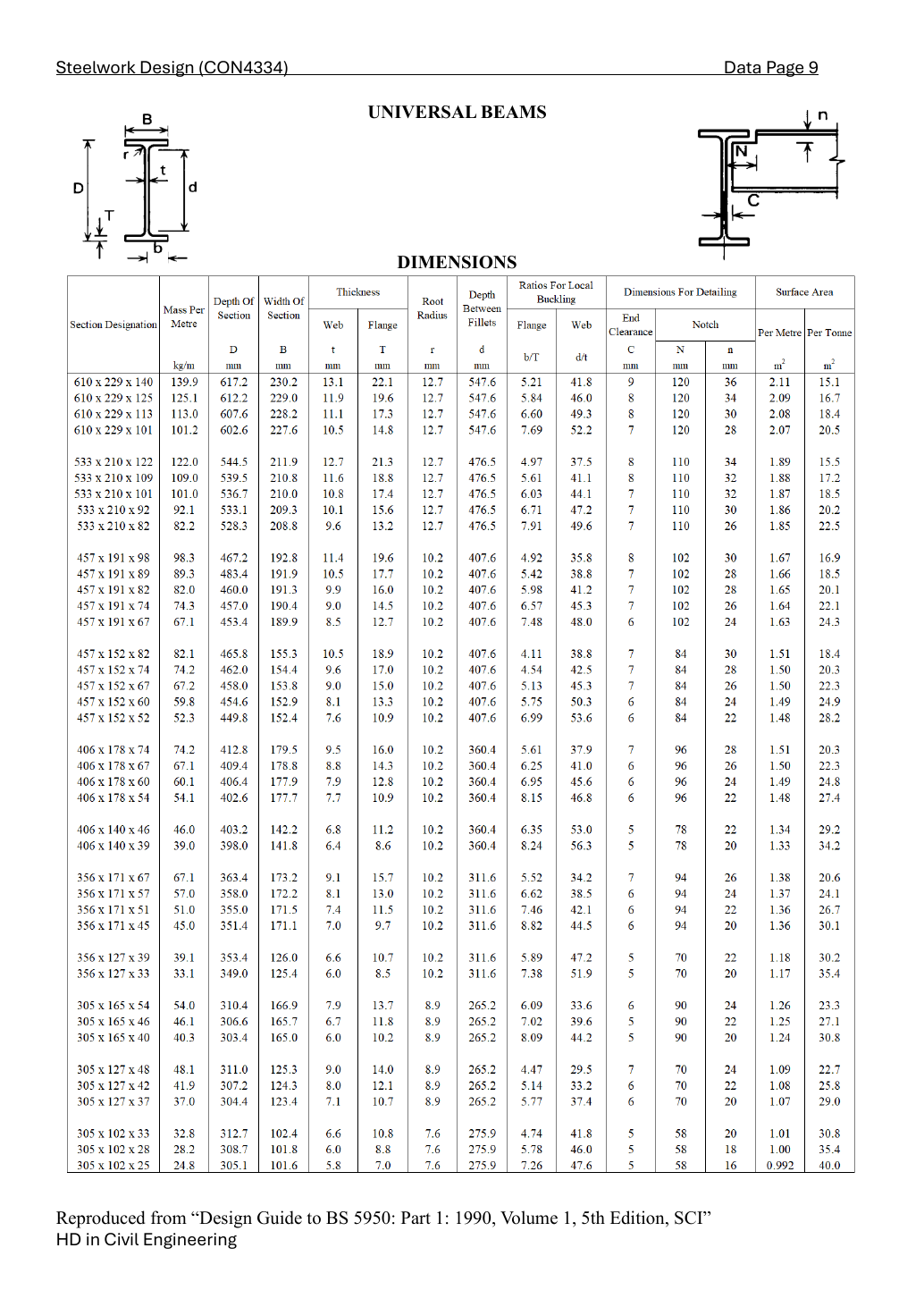
Lookup the exact 457 × 191 × 82 UB row. Read dimensions first, properties second. D = overall depth; t = web thickness; T = flange thickness; d = clear web depth. The designation is not an exact dimension.
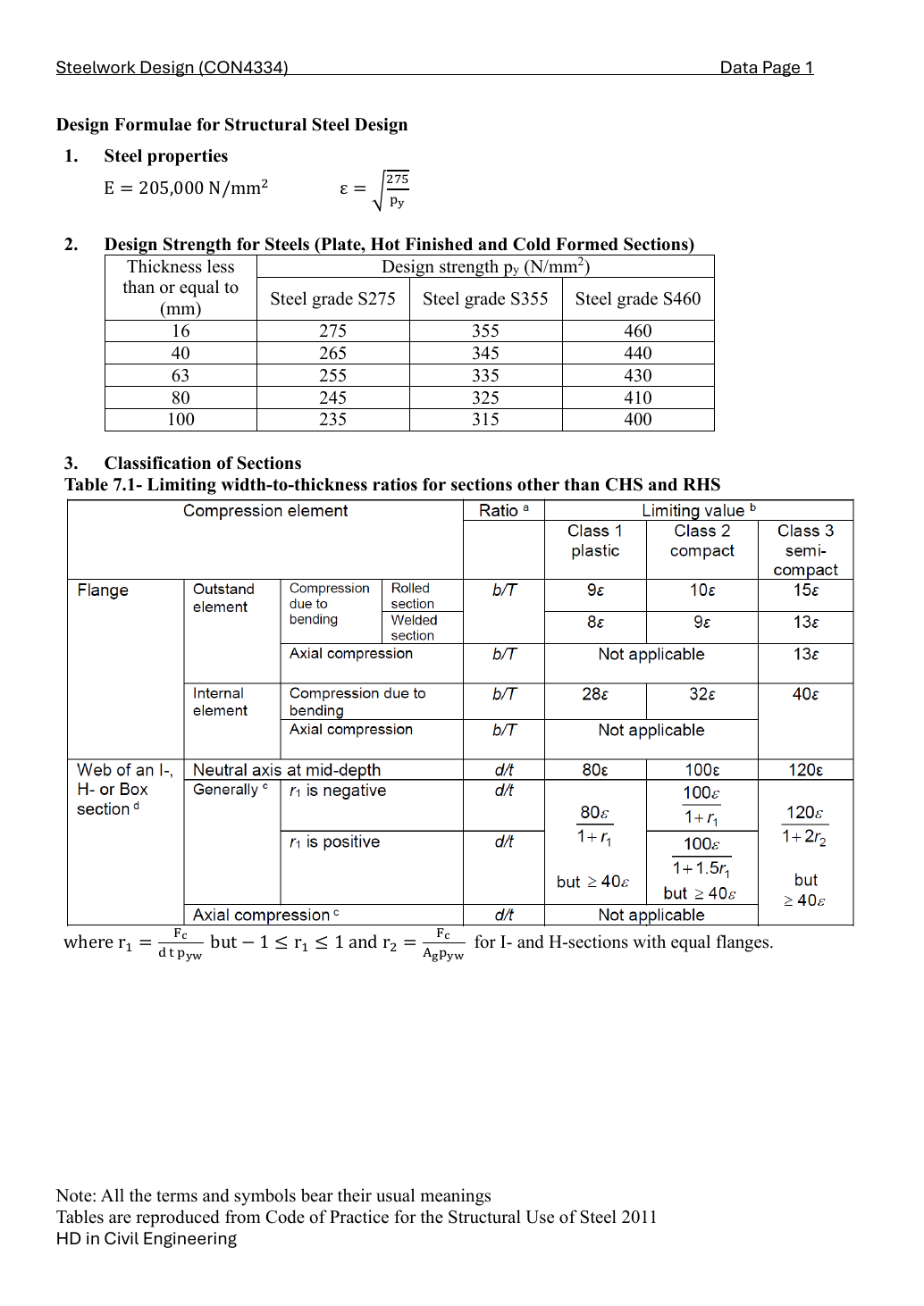
S355 design strength depends on the actual flange thickness. Local classification decides whether plastic bending resistance is allowed. In pure bending the web limit is different from uniform compression.
py=355N/mm2,ϵ=275/355=0.880141
b/T=5.98,9ϵ=7.921,10ϵ=8.801,13ϵ=11.442
d/t=41.2<80ϵ=70.411⟹Class1
Take the worse flange/web class. Class 1 or 2 permits the capped plastic modulus; Class 3 uses the elastic modulus.
Support reactions [3 marks]
Take moments about the left support to eliminate RA, then sum vertical forces. An applied counter-clockwise end couple contributes positively to the external moment balance and is subtracted when solving for RB.
RBL+80−wL2/2−∑Piai=0
RB=92(9)2/2+60(4.5)−80=30.111111kN
RA=2(9)+60−30.111111=47.888889kN
RA+RB=78kN=wL+∑Pi
The right-hand arrow is counter-clockwise, C = +80 kN·m. A pin/roller has no reaction moment, but an externally applied couple still makes the beam-end internal moment nonzero.
Compact exam answer — key result lines
RBL+80−wL2/2−∑Piai=0
RB=92(9)2/2+60(4.5)−80=30.111111kN
RA=2(9)+60−30.111111=47.888889kN
RA+RB=78kN=wL+∑Pi
The right-hand arrow is counter-clockwise, C = +80 kN·m. A pin/roller has no reaction moment, but an externally applied couple still makes the beam-end internal moment nonzero.
Shear-force and bending-moment diagrams [4 marks]
Cut the beam at distance x. Keep only loads to the left of the cut. A point load drops the SFD by its magnitude; the UDL gives slope −w. The BMD is the integral of shear, so it is continuous through a point force and curved under a UDL. Maximum moment can occur at a shear sign change or at a loaded/coupled boundary.
V(x)=RA−wx−ai<x∑Pi(kN)
M(x)=RAx−wx2/2−i∑Pimax(0,x−ai)(kNm)
M(x)=47.888889x−2x2/2−60max(0,x−4.5)
x (m)
V just left (kN)
V just right (kN)
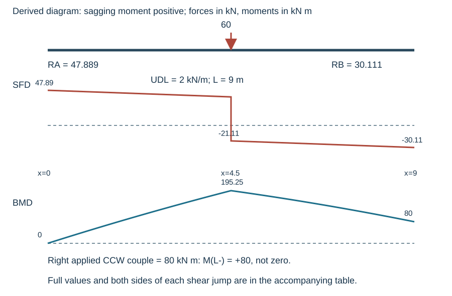
M (kN m)
0
47.888889
47.888889
0
4.5
38.888889
-21.111111
195.25
9
-30.111111
-30.111111
80
At the end supports the table gives the internal beam-side value; the external SFD closes to zero after including the reaction. At an internal zero-shear point, substitute x = (RA − preceding point loads)/w when that x lies within the interval.
Calculated SFD and BMD; point-load jumps, UDL curvature and labelled ordinates. Full-size imageCompact exam answer — key result lines
V(x)=RA−wx−ai<x∑Pi(kN)
M(x)=RAx−wx2/2−i∑Pimax(0,x−ai)(kNm)
M(x)=47.888889x−2x2/2−60max(0,x−4.5)
At the end supports the table gives the internal beam-side value; the external SFD closes to zero after including the reaction. At an internal zero-shear point, substitute x = (RA − preceding point loads)/w when that x lies within the interval.
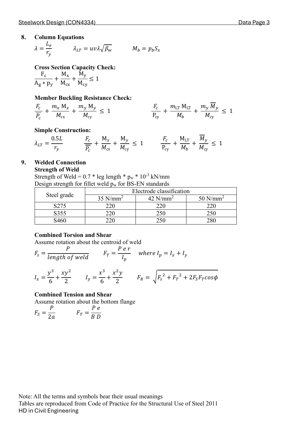
LTB: restraint positions 0, 4.5, 9 m [14 marks]
Check the segment x = 0 to 4.5 m. Its length is 4.5 m; the largest |M| occurs at x = 4.5 m.
For this restraint segment, take the absolute moments at its quarter, half and three-quarter points; divide by the largest absolute moment anywhere in the same segment. The stations belong to the segment, not necessarily to the whole beam. Apply the lower bound 0.44.
Use the stated normal-loading effective-length branch: LE equals the distance between effective lateral/torsional restraints. A restraint does not create a new vertical support. Class 1/2 gives βW = 1.
For this restraint segment, take the absolute moments at its quarter, half and three-quarter points; divide by the largest absolute moment anywhere in the same segment. The stations belong to the segment, not necessarily to the whole beam. Apply the lower bound 0.44.
Use the stated normal-loading effective-length branch: LE equals the distance between effective lateral/torsional restraints. A restraint does not create a new vertical support. Class 1/2 gives βW = 1.
For this restraint segment, take the absolute moments at its quarter, half and three-quarter points; divide by the largest absolute moment anywhere in the same segment. The stations belong to the segment, not necessarily to the whole beam. Apply the lower bound 0.44.
Use the stated normal-loading effective-length branch: LE equals the distance between effective lateral/torsional restraints. A restraint does not create a new vertical support. Class 1/2 gives βW = 1.
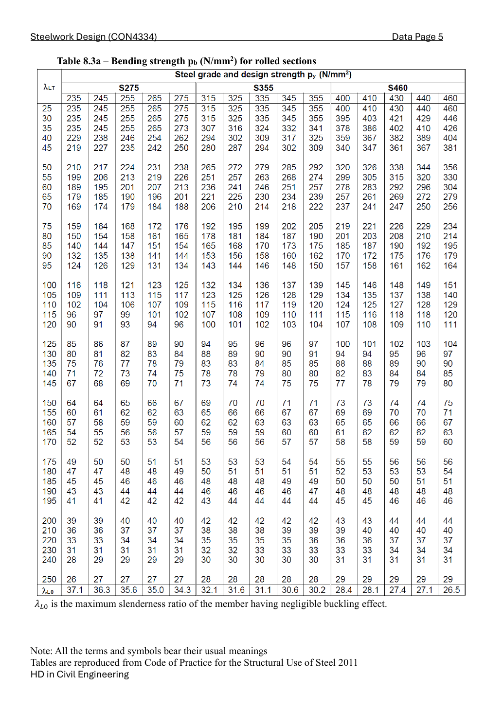
Table 8.3, py = 355 N/mm² column; bracketing λLT rows 135 and 140. Interpolate in this column only.
pb=85+140−135137.71305−135(80−85)=82.28695N/mm2
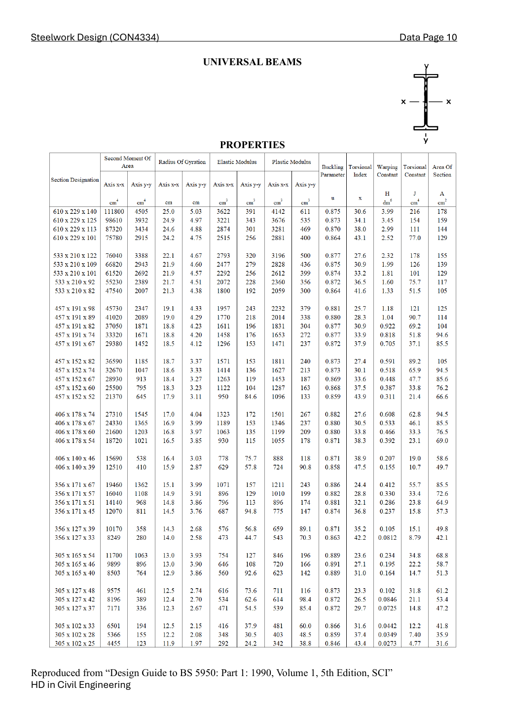
Mb=pbSx/1000=82.28695(1831)/1000=150.667405kNm
mLTMmax=0.888508(195.25)=173.48125kNm
ηLT=173.48125/150.667405=1.151419
FAIL
Every listed segment must pass. Do not compare the whole-beam maximum with a short segment’s capacity unless that maximum occurs in that segment.
Compact exam answer — key result lines
λLT=uvλ=0.877(0.738029)(212.765957)=137.71305
pb=85+140−135137.71305−135(80−85)=82.28695N/mm2
Mb=pbSx/1000=82.28695(1831)/1000=150.667405kNm
mLTMmax=0.888508(195.25)=173.48125kNm
ηLT=173.48125/150.667405=1.151419
Every listed segment must pass. Do not compare the whole-beam maximum with a short segment’s capacity unless that maximum occurs in that segment.
Reusable procedure and traps
Separate ultimate resistance from imposed-load serviceability. Keep kN/m and mm-based formulas consistent.
Establish the whole-beam reactions first. For each restraint segment use its own length, quarter-point moments and maximum moment.
A high Mc does not prove LTB passes. Check mLT M ≤ Mb as well as the applicable section resistance.
A smaller unrestrained length normally increases Mb, but its moment factor changes too; recalculate rather than scaling the old ratio.
Independent practice — invented variant
Invented variant: add a lateral brace at a quarter-span point without changing vertical supports or loads. Which calculations change?
Hint
Separate the vertical-load model from the lateral-restraint model.
Reveal answer
Reactions, SFD, BMD and vertical-load deflection remain unchanged in this ideal restraint model. Create new LTB segments, then recalculate each LE, quarter-station moments, mLT, λLT, pb and utilisation. The brace needs a stable load path and cannot be treated as a new vertical support.