Steelwork · Exam learning

2014–2019 · Reference answers

2015-01-03 — connection answers

All connection subparts from this paper, including the specified checks and source qualifications.

Independent teaching answer, not an official solution or marking scheme. Printed marks are retained. Read the source conditions beside each result.

Recognise the connection model

Units: 1 kN = 1,000 N; 1 m = 1,000 mm; 1 cm³ = 1,000 mm³; 1 cm⁴ = 10,000 mm⁴. A demand is the load effect; a resistance is what the member can carry. Compare matching units.

A splice transfers axial force through stages. A side-plate bracket creates in-plane torsion. An end-plate bracket creates bolt tension. Identify which picture applies before selecting a formula.

Complete splice check [18 marks]

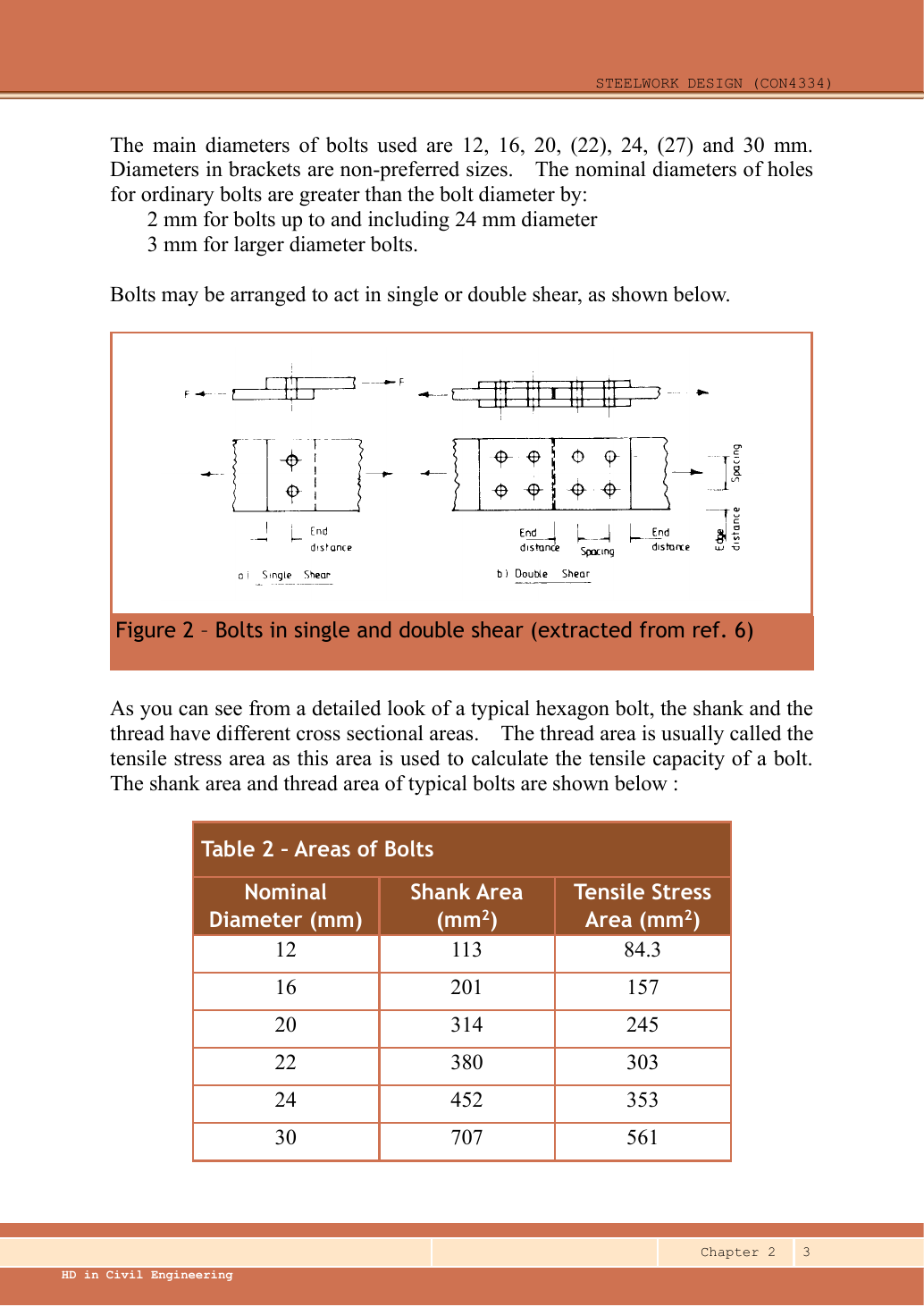
Given main plate 20 mm, two covers each 10 mm, Grade 8.8 M16 bolts with 18 mm holes. The transverse dimension chain gives main width 120 mm and cover width 120 mm. Count 6 bolts on ONE side of the butt. The other side is in series and does not double the transferable force.

Source: LectureNotes/Ch2_Connection.pdf · p.3, p.4, p.5, p.9, p.10
Source: LectureNotes/CON4334-Data File-20260730.pdf · p.1, p.4

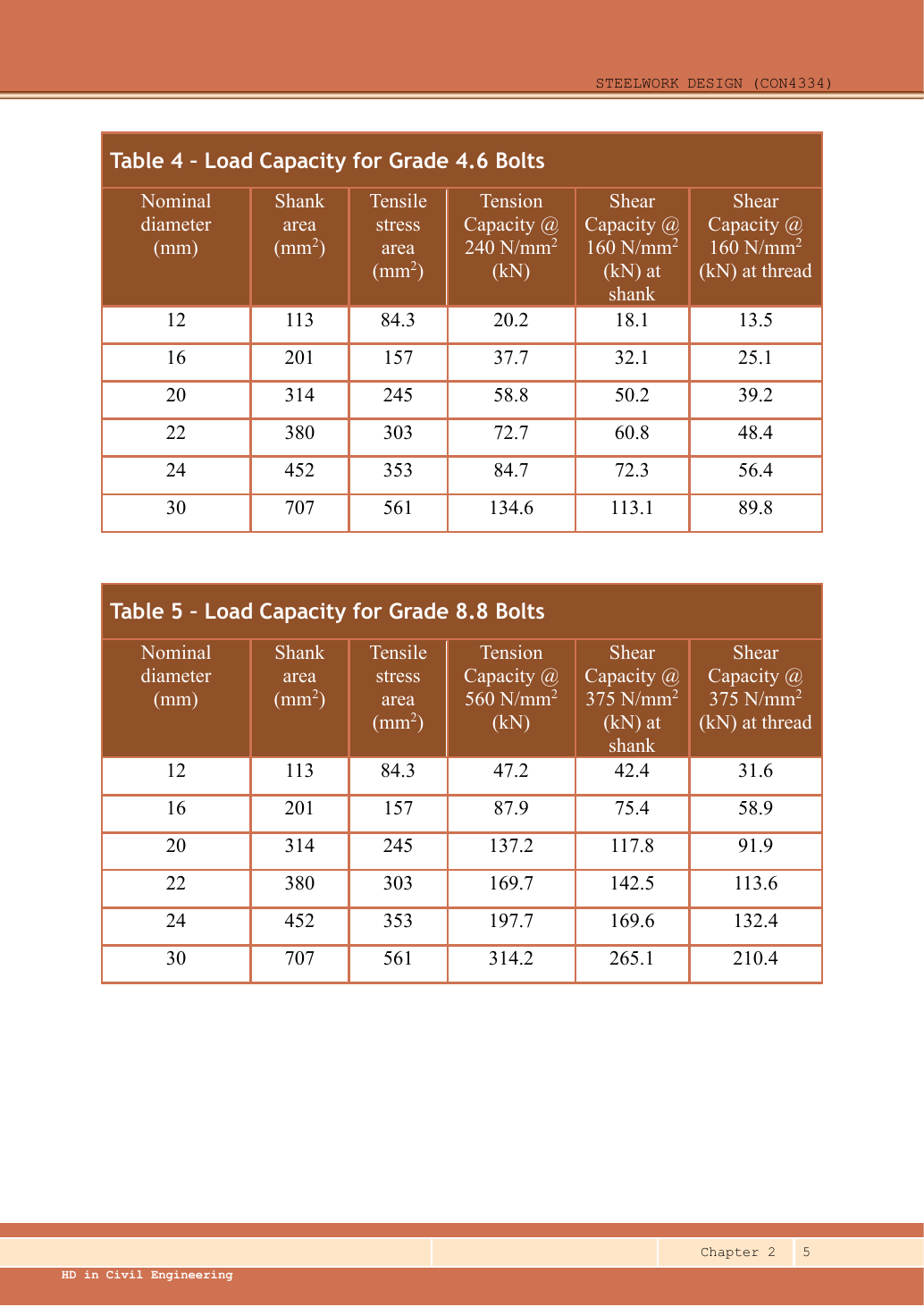
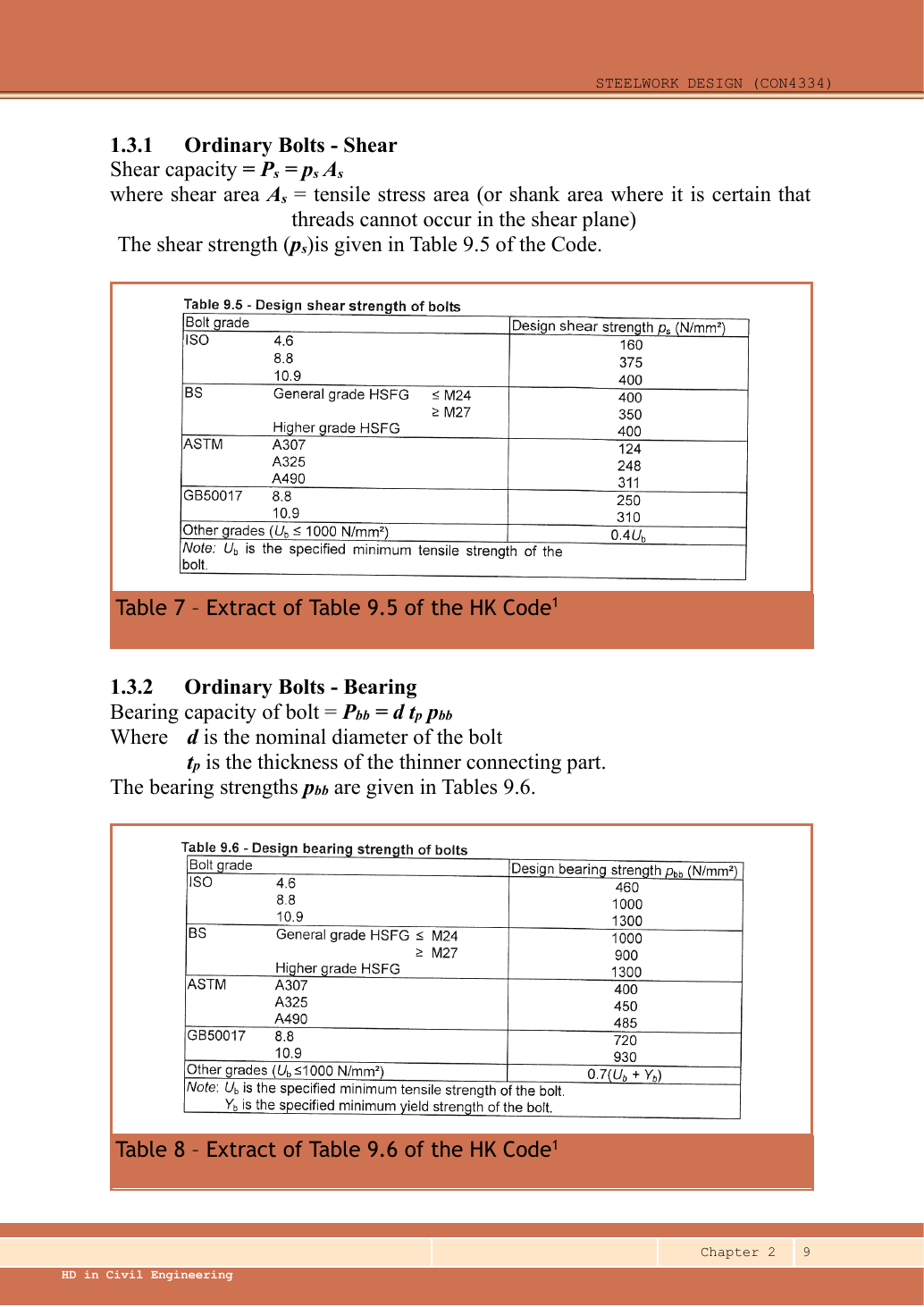
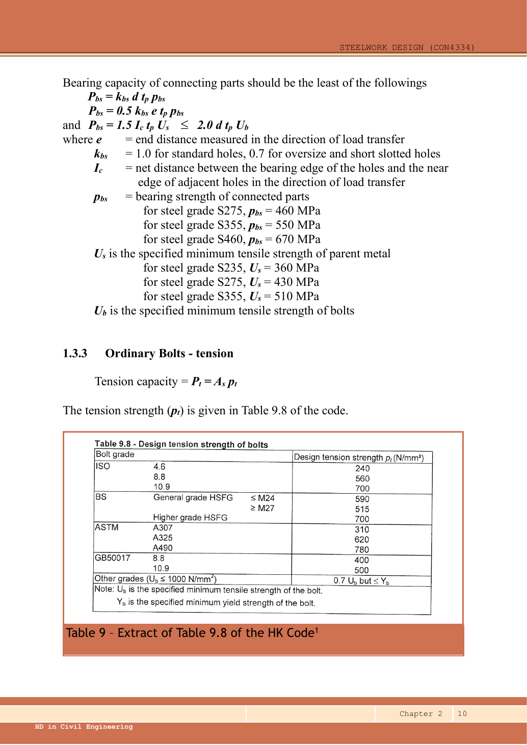
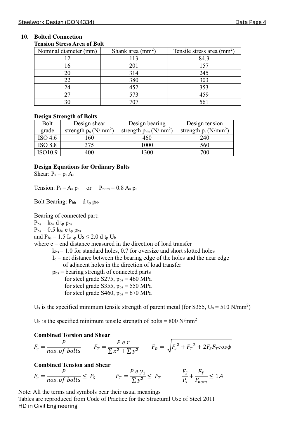
Grade 8.8: shear strength ps = 375, bolt bearing pbb = 1000, ultimate bolt strength Ub = 800 N/mm². S355 plate: pbs = 550, Us = 510 N/mm², Ke = 1.1. Use threaded stress area As for the conservative shear plane, nominal d for bearing, and hole diameter d0 for material removed.

Simple explanation — open only if needed

The force must cross the left bolt group, travel through the covers, then cross the right group. The weakest stage limits the whole splice, like the weakest link in a chain.

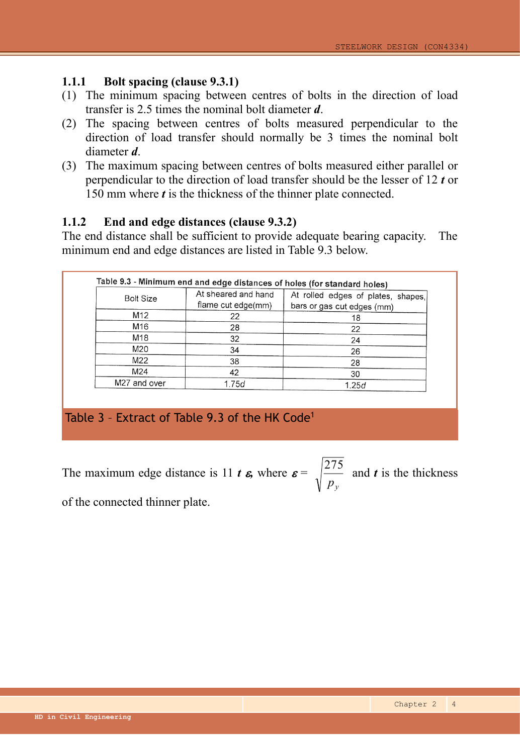
This checks the requested resistance modes. Check edge preparation and ordinary minimum pitch separately; a bearing pass alone does not prove all detailing.

Ps,plane=Asps/1000=157(375)/1000=58.875 kNP_{s,plane}=A_sp_s/1000=157(375)/1000=58.875\,\mathrm{kN}
Ps,bolt=2(58.875)=117.75 kN,Rs=6(2)(58.875)=706.5 kNP_{s,bolt}=2(58.875)=117.75\,\mathrm{kN},\quad R_s=6(2)(58.875)=706.5\,\mathrm{kN}

Each bolt has two shear planes, one at each cover/main interface.

tbearing=min⁡(20,2(10))=20 mmt_{bearing}=\min(20,2(10))=20\,\mathrm{mm}
Pbb=dtbearingpbb/1000=16(20)(1000)/1000=320 kN/boltP_{bb}=dt_{bearing}p_{bb}/1000=16(20)(1000)/1000=320\,\mathrm{kN/bolt}
Rbb=6(320)=1920 kNR_{bb}=6(320)=1920\,\mathrm{kN}

Main plate

Rbs=min⁡(dtpbs,0.5etpbs,1.5lctUs,2dtUb)/1000R_{bs}=\min(dt p_{bs},0.5etp_{bs},1.5l_ctU_s,2dtU_b)/1000
lc=p−d0=50−18=32 mml_c=p-d_0=50-18=32\,\mathrm{mm}
Rbs=min⁡(16(20)(550),0.5(35)(20)(550),1.5(32)(20)(510),2(16)(20)(800))/1000R_{bs}=\min(16(20)(550),0.5(35)(20)(550),1.5(32)(20)(510),2(16)(20)(800))/1000
Rbs=min⁡(176,192.5,489.6,512)=176 kN/boltR_{bs}=\min(176,192.5,489.6,512)=176\,\mathrm{kN/bolt}

Each cover plate

Rbs=min⁡(dtpbs,0.5etpbs,1.5lctUs,2dtUb)/1000R_{bs}=\min(dt p_{bs},0.5etp_{bs},1.5l_ctU_s,2dtU_b)/1000
lc=p−d0=50−18=32 mml_c=p-d_0=50-18=32\,\mathrm{mm}
Rbs=min⁡(16(10)(550),0.5(35)(10)(550),1.5(32)(10)(510),2(16)(10)(800))/1000R_{bs}=\min(16(10)(550),0.5(35)(10)(550),1.5(32)(10)(510),2(16)(10)(800))/1000
Rbs=min⁡(88,96.25,244.8,256)=88 kN/boltR_{bs}=\min(88,96.25,244.8,256)=88\,\mathrm{kN/bolt}
Rmain,bearing=6(176)=1056 kN,Rcovers,bearing=2(6)(88)=1056 kNR_{main,bearing}=6(176)=1056\,\mathrm{kN},\quad R_{covers,bearing}=2(6)(88)=1056\,\mathrm{kN}

Main plate, two holes across the critical transverse section.

Ag=bt=120(20)=2400 mm2,An=(b−2d0)t=(120−2(18))(20)=1680 mm2A_g=bt=120(20)=2400\,\mathrm{mm^2},\quad A_n=(b-2d_0)t=(120-2(18))(20)=1680\,\mathrm{mm^2}
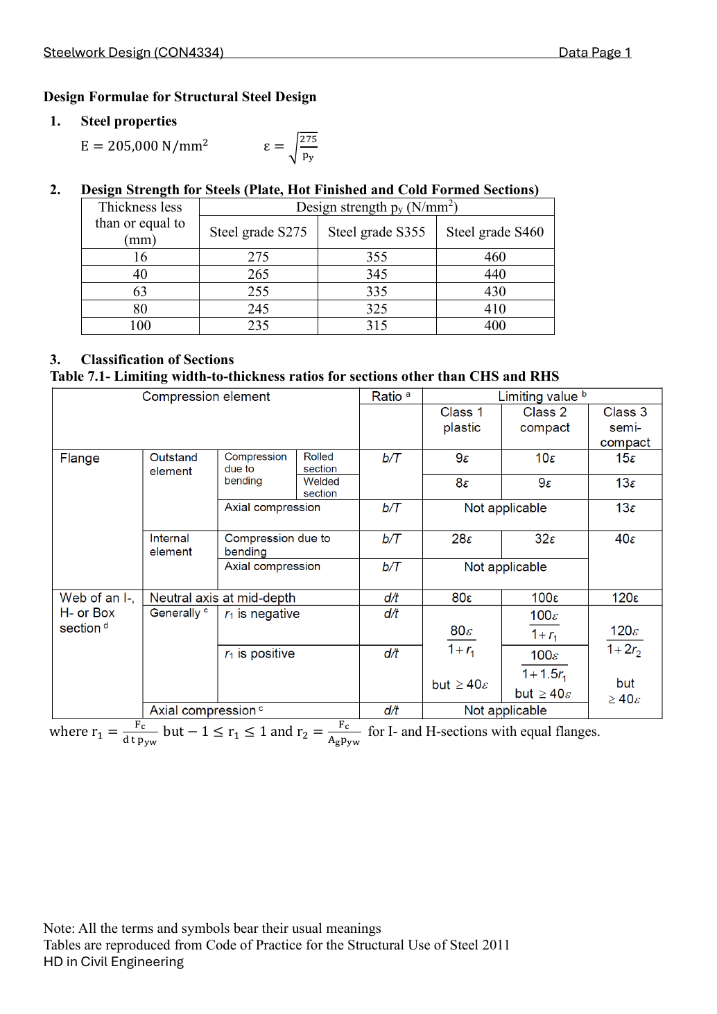
Ae=min⁡(Ag,KeAn)=min⁡(2400,1.1(1680))=1848 mm2A_e=\min(A_g,K_eA_n)=\min(2400,1.1(1680))=1848\,\mathrm{mm^2}
Pt=pyAe/1000=345(1848)/1000=637.56 kNP_t=p_yA_e/1000=345(1848)/1000=637.56\,\mathrm{kN}

Each cover plate: use its own width and thickness.

Ag=bt=120(10)=1200 mm2,An=(b−2d0)t=(120−2(18))(10)=840 mm2A_g=bt=120(10)=1200\,\mathrm{mm^2},\quad A_n=(b-2d_0)t=(120-2(18))(10)=840\,\mathrm{mm^2}
Ae=min⁡(Ag,KeAn)=min⁡(1200,1.1(840))=924 mm2A_e=\min(A_g,K_eA_n)=\min(1200,1.1(840))=924\,\mathrm{mm^2}
Pt=pyAe/1000=355(924)/1000=328.02 kNP_t=p_yA_e/1000=355(924)/1000=328.02\,\mathrm{kN}
Pt,covers=2(328.02)=656.04 kNP_{t,covers}=2(328.02)=656.04\,\mathrm{kN}
Rsplice=min⁡(706.5,1920,1056,1056,637.56,656.04)=637.56 kNR_{splice}=\min(706.5,1920,1056,1056,637.56,656.04)=637.56\,\mathrm{kN}
P=600 kN,P/Rsplice=0.941088P=600\,\mathrm{kN},\quad P/R_{splice}=0.941088

PASS

Compact exam answer — key result lines
Ae=min⁡(Ag,KeAn)=min⁡(1200,1.1(840))=924 mm2A_e=\min(A_g,K_eA_n)=\min(1200,1.1(840))=924\,\mathrm{mm^2}
Pt=pyAe/1000=355(924)/1000=328.02 kNP_t=p_yA_e/1000=355(924)/1000=328.02\,\mathrm{kN}
Pt,covers=2(328.02)=656.04 kNP_{t,covers}=2(328.02)=656.04\,\mathrm{kN}
Rsplice=min⁡(706.5,1920,1056,1056,637.56,656.04)=637.56 kNR_{splice}=\min(706.5,1920,1056,1056,637.56,656.04)=637.56\,\mathrm{kN}
P=600 kN,P/Rsplice=0.941088P=600\,\mathrm{kN},\quad P/R_{splice}=0.941088

PASS

UB bracket welds [12 marks]

Source: LectureNotes/Ch2_Connection.pdf · p.31, p.33, p.41
Source: LectureNotes/CON4334-Data File-20260730.pdf · p.9, p.10

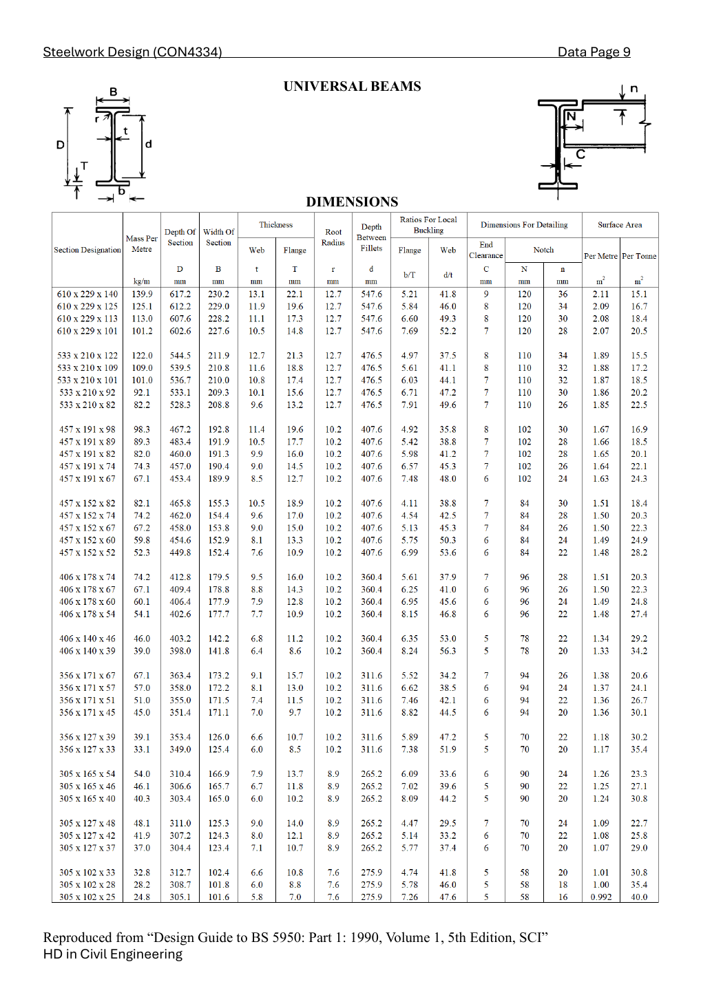
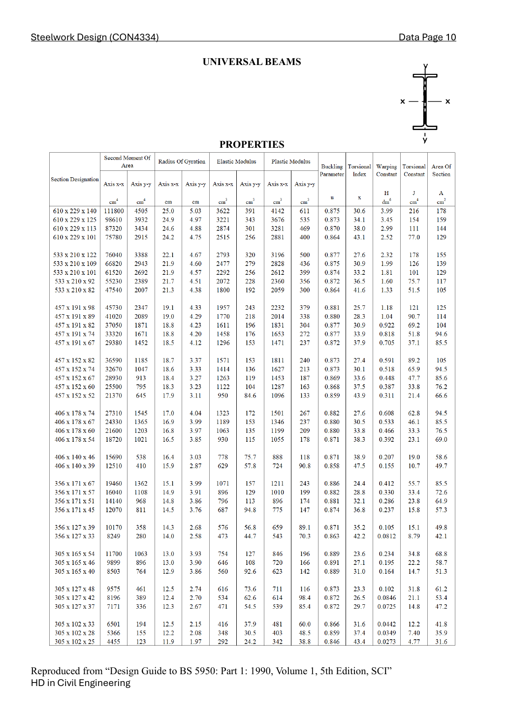
Lookup the exact 406 × 178 × 60 UB row. Read dimensions first, properties second. D = overall depth; t = web thickness; T = flange thickness; d = clear web depth. The designation is not an exact dimension.

D=406.4, t=7.9, T=12.8, d=360.4(mm)D=406.4,\ t=7.9,\ T=12.8,\ d=360.4\quad(\mathrm{mm})
b/T=6.95, d/t=45.6, Ix=21600 cm4, Zx=1063 cm3, Sx=1199 cm3b/T=6.95,\ d/t=45.6,\ I_x=21600\,\mathrm{cm^4},\ Z_x=1063\,\mathrm{cm^3},\ S_x=1199\,\mathrm{cm^3}
ry=39.7 mm,u=0.88,x=33.8r_y=39.7\,\mathrm{mm},\quad u=0.88,\quad x=33.8

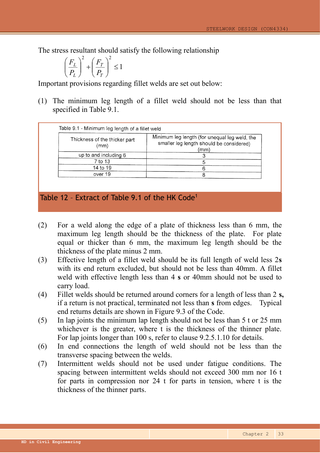
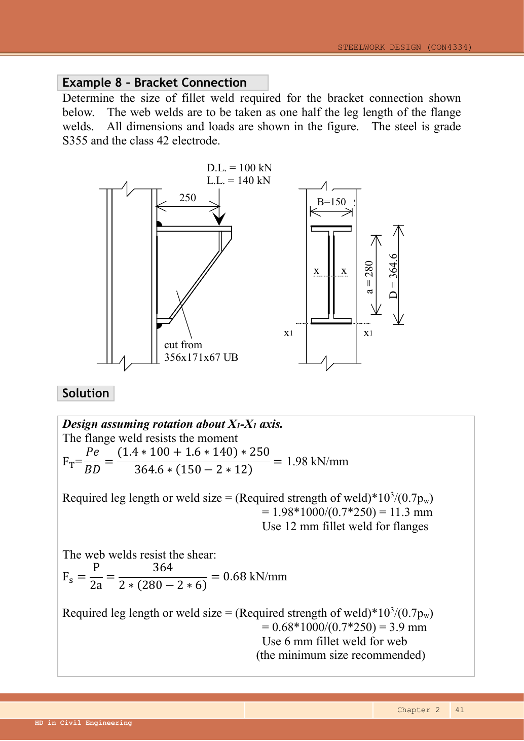
Follow the specified separated model: the two web welds carry all shear; the upper and lower flange welds form a force couple carrying moment. The web-weld length is not the couple arm. Use the smaller flange-centroid separation D−T conservatively because the exact weld-centroid spacing is not dimensioned.

P=350 kN,M=Pe=350(350)=122500 kN mmP=350\,\mathrm{kN},\quad M=Pe=350(350)=122500\,\mathrm{kN\,mm}
z=D−T=406.4−12.8=393.6 mm,Ff=M/z=122500/393.6=311.229675 kNz=D-T=406.4-12.8=393.6\,\mathrm{mm},\quad F_f=M/z=122500/393.6=311.229675\,\mathrm{kN}

For a strength trial choose a 350 mm physical web run within the 360.4 mm clear web; this length is designed, not printed. Try 5 mm web fillets and 14 mm flange fillets, then check the independent detailing constraints.

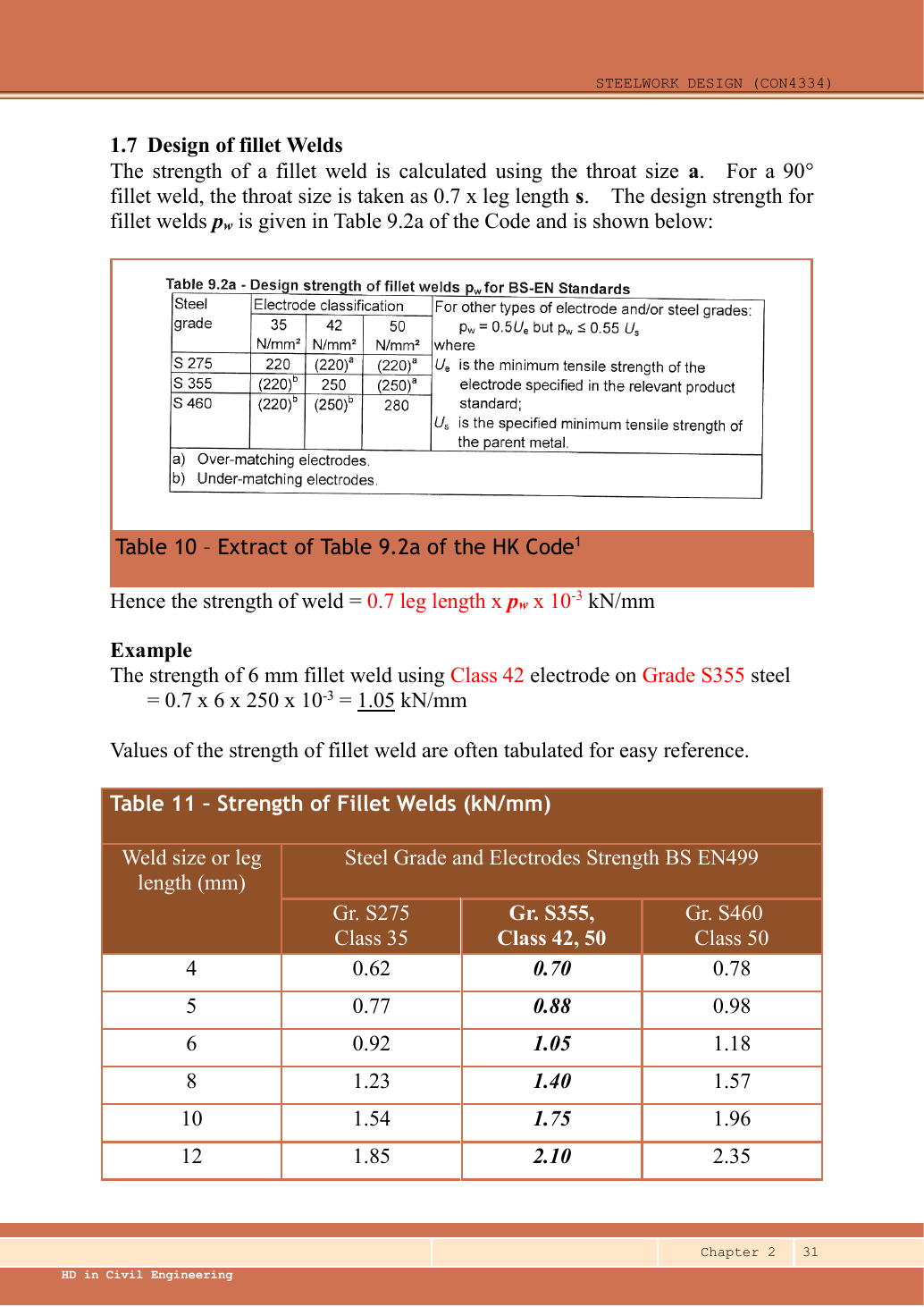
Vw,Rd=2(350−2(5))(0.7)(5)(250)/1000=595 kNV_{w,Rd}=2(350-2(5))(0.7)(5)(250)/1000=595\,\mathrm{kN}

PASS

Ff,Rd=(170−2(14))(0.7)(14)(250)/1000=347.9 kNF_{f,Rd}=(170-2(14))(0.7)(14)(250)/1000=347.9\,\mathrm{kN}

PASS

sweb,max=t−2=7.9−2=5.9 mm,sflange,max=T−2=12.8−2=10.8 mms_{web,max}=t-2=7.9-2=5.9\,\mathrm{mm},\quad s_{flange,max}=T-2=12.8-2=10.8\,\mathrm{mm}
Rflange,edge max=(170−2(10.8))(0.7)(10.8)(250)/1000=280.476 kN<FfR_{flange,edge\ max}=(170-2(10.8))(0.7)(10.8)(250)/1000=280.476\,\mathrm{kN}<F_f

The strength trial is not a permissible ordinary flange-edge fillet: even the maximum permitted leg cannot carry the required flange force in the shown single-run arrangement. Increase weld extent/add a suitably designed second run, change the section or provide an appropriate prepared connection; do not report 14 mm as a completed design.

Compact exam answer — key result lines
z=D−T=406.4−12.8=393.6 mm,Ff=M/z=122500/393.6=311.229675 kNz=D-T=406.4-12.8=393.6\,\mathrm{mm},\quad F_f=M/z=122500/393.6=311.229675\,\mathrm{kN}
Vw,Rd=2(350−2(5))(0.7)(5)(250)/1000=595 kNV_{w,Rd}=2(350-2(5))(0.7)(5)(250)/1000=595\,\mathrm{kN}
Ff,Rd=(170−2(14))(0.7)(14)(250)/1000=347.9 kNF_{f,Rd}=(170-2(14))(0.7)(14)(250)/1000=347.9\,\mathrm{kN}
sweb,max=t−2=7.9−2=5.9 mm,sflange,max=T−2=12.8−2=10.8 mms_{web,max}=t-2=7.9-2=5.9\,\mathrm{mm},\quad s_{flange,max}=T-2=12.8-2=10.8\,\mathrm{mm}
Rflange,edge max=(170−2(10.8))(0.7)(10.8)(250)/1000=280.476 kN<FfR_{flange,edge\ max}=(170-2(10.8))(0.7)(10.8)(250)/1000=280.476\,\mathrm{kN}<F_f

The strength trial is not a permissible ordinary flange-edge fillet: even the maximum permitted leg cannot carry the required flange force in the shown single-run arrangement. Increase weld extent/add a suitably designed second run, change the section or provide an appropriate prepared connection; do not report 14 mm as a completed design.

Reusable procedure and common errors

  1. Draw the load-transfer stages. Count bolts and shear planes for one stage, then compare all failure modes.
  2. Resolve eccentric forces as vectors. Never add perpendicular components arithmetically.
  3. Use effective weld length and check size limits after strength; “strong enough” does not fix an impossible detail.

Independent practice — invented variant

Invented variant: all applied loads are 10% larger but geometry is unchanged. What scales, and what does not?

Hint

Isolate one load-transfer stage, then distinguish demand from fixed resistance.

Reveal answer

For these linear elastic models, bolt forces and weld force per unit length rise 10%; required strength-only weld throat also rises 10%. Bolt areas, section capacities, effective lengths of already specified welds and detailing limits stay unchanged. Recheck every utilisation.